SIMATIC S7-300 Digital module SM 323 isolated 16 DI and 16 DO 24 V DC 05 A Total current 4A 1x 40-pole. Wiring and commissioning of the SIMATIC S7- 1500 and ET 200MP systems.
6es7321 1bl00 0aa0 Wiring Diagram - If you're searching for picture and video information related to the keyword you've come to pay a visit to the ideal site. Our site gives you hints for seeing the highest quality video and image content, search and find more informative video articles and graphics that fit your interests. comprises one of tens of thousands of movie collections from various sources, especially Youtube, therefore we recommend this video for you to see. You can also contribute to supporting this site by sharing videos and images that you enjoy on this blog on your social networking accounts such as Facebook and Instagram or tell your closest friends share your experiences about the simplicity of access to downloads and the information you get on this site. This blog is for them to visit this website.

Digital Input Module Sm 321 Di 64 X Dc 24 V Sinking Sourcing 6es7321 1bp00 0aa0 Id 8859629 Industry Support Siemens
Preface S7-300 Module data 6 Manual 022013 A5E00105505-08 Standards See section Standards and approvals Page 15.

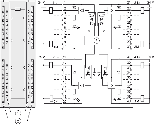
6es7321 1bl00 0aa0 wiring diagram. 6ES7 322-1BL00-0AA0 6ES7 322-1CF80-0AA0 6ES7 322-1FF01-0AA0. EWA 4NEB 710 6067-02 01 Terminal Connection Diagram and Block Diagram Figure 1-1 shows the terminal connection diagram and block diagram of the digital input module SM 321. Ad 78 in stock.
Recycling and disposal Since the S7-300 components only contain low levels of harmful substances they are. SM 323SM 327 digital inputoutput modules. Suitable for switches and 234-wire BEROs proximity switches.
Manual 02 A5E. 6ES7 BHAA0 Wiring diagram of PS. 6es7 331-7kf02-0ab0 wiring manual.
Please find attached wiring diagram and suggest any correction in it. AO 4 x 12 bits Current output QI0 MANA QI1 MANA QI2 MANA QI3 MANA CH0 CH1 CH2 CH3 Voltage outputs QV0 S0 S0 MANA QV1 S1 S1 MANA QV2 S2 S2 MANA QV3 S3 S3 MANA CH0 CH1 CH2 CH3 SF Fault indicator red Internal supply Isolation Backplane bus interface SF L 24V DAC M M. Terminal connection and block diagram of analog output module SM 332.
Device information Pro duct manuals contain a compact description of the module- specific information such as properties wiring diagrams characteristics and technical specifications. Product data sheet 6ES7321-1BH02-0AA0-SIMATIC S7-300 DIGITAL INPUT SM 321 OPTICALLY ISOLATED 16DI 24 V DC 1 X 20 PIN Supply voltage Load voltage L Rated value DC 24V permissible range lower limit DC 204V permissible range upper limit DC 288V Input current from backplane bus 5 V DC max. DI 16 48 to 125 VDC.
Properties wiring diagrams characteristics and technical specifications. 4 May 2011 This manual contains notices intended to ensure personal safety as well as to protect the. Properties wiring diagrams characteristics and technical specifications.
6ES7522-1BL00-0AB0 Manual 092016 A5E03485060-AD Preface Documentation guide 1 Product overview 2 Wiring 3 Parametersaddress space 4. Article Number Market Facing Number 6ES7323-1BL00-0AA0. 15mA Power loss Power loss typ.
2Digital Output module. For more information on front connector wiring and creating cable shields for example refer. Product Lifecycle PLM PM300Active Product.
Digital inputoutput module DI 16x24VDCDQ 16x24VDC05A BA 6ES75231BL00- -0AA0. 6ES7523-1BL00-0AA0 Manual 092016 A5E32364588-AC Preface Documentation guide 1 Product overview 2 Wiring 3 Address space 4 Diagnostics alarms 5. The diagram below shows the structure of data record 1 of SM.
Digital input module di 16x24vdc ba 6es7521 1bh10 0aa0 32x24vdc 1bl10 hf 1bl00 0ab0 how to wire discrete dc sensors plc part 1 realpars diagram wiring output card full version hd quality mediagrame arsae it profibus connector siemens s7 300 diagrams signals techniques i o imdiagram lavocedelmare diagramrt strabrescia read a control panel upmation io connection 1214c entries. 10mA Power loss Power loss. 3 AnalogInput module.
Digital input module DI 32x24VDC BA 6ES75211BL10- -0AA0 Manual 092014 A5E32363711-AB 11 Wiring 3 31 Wiring and block diagram This section contains the block diagram of the module and outlines various connection options. AI 8 x RTD. 6es7331-1kf01-0ab0 manual6es7321-1fh00-0aa0 wiring diagram.
I need to verify the wiring of. Ad 78 in stock. The STEP 7 online help supports you in the configuration and programming.
Product data sheet 6ES7321-1BL00-0AA0-SIMATIC S7-300 DIGITAL INPUT SM 321 OPTICALLY ISOLATED 32DI 24 V DC 1 X 40 PIN Supply voltage Load voltage L Rated value DC 24V permissible range lower limit DC 204V permissible range upper limit DC 288V Input current from backplane bus 5 V DC max. I have prepared wiring diagrams for these above modules. Buy Siemens SIMATIC S Series Input Relay Module 16 Inputs V dc x 40 x mm 6ESBHAA0.
Productdatablad 6ES7321-1BL00-0AA0-SIMATIC S7-300 DIGITAL INPUT SM 321 OPTICALLY ISOLATED 32DI 24 V DC 1 X 40 PIN Supply voltage Load voltage L Rated value DC 24V permissible range lower limit DC 204V permissible range upper limit DC 288V Input current from backplane bus 5 V DC max. DQ 32x24VDC05A ST Digital Output Module 6ES75221BL00- -0AB0. 6es7 331-1kf02-0ab0 wiring manual.
1 Im after complete wiring drawing which shows pinwise arrangement of the following. 1 Digital Input module.

Profibus Connector 6es7321 1bh02 0aa0

6es7322 1bl00 0aa0 Pdf Electrical Connector Voltage

Profibus Connector Digital Input

Profibus Connector Blog Archive 6es7322 1bl00 0aa0 Siemens Digital Output Module
6es7321 1bl00 0aa0 Connectique Tension Electrique
Digital Output Module Sm 322 Do 32 X Dc 24 V 0 5 A 6es7322 1bl00 0aa0 Simatic Id 8859629 Industry Support Siemens
Https Support Industry Siemens Com Cs Attachments 59192896 S71500 Di 32x24vdc Hf Manual En Us En Us Pdf Download True

Profibus Connector 6es7323 1bl00 0aa0
6es7322 1bl00 0aa0
