The connection diagram is printed on. 6es7 331-1kf02-0ab0 wiring manual.
6es73311kf020ab0 Wiring Diagram - If you're searching for picture and video information related to the keyword you've come to visit the right site. Our website provides you with hints for seeing the maximum quality video and image content, hunt and find more enlightening video content and graphics that match your interests. comprises one of thousands of video collections from several sources, especially Youtube, so we recommend this video for you to view. This blog is for them to stop by this website.

Profibus Connector 6es7331 1kf02 0ab0
240 mA from backplane bus 5 V DC.

6es73311kf020ab0 wiring diagram. SIMATIC S7-300 ANALOG INPUT SM 331 OPT. Siemens S7 300 Plc Wiring Diagram Pdf. DO 8 x DC 24 V2 A - Technical data Technical data Dimensions and weight Dimensions W x H x D mm 40 x 125 x 117 Weight approx.
6ES7331-1KF02-0AB0 S7-300 Module data 300 Manual 082009 A5E00105505-06 Wiring. ISOL234 WIRE 8AI RESISTANCE PT1002001000 NI1001202005001000 CU10 PLUS CHARACTERISTICS ACCORDING TO GOST STANDARD 16 INTERN 24 BIT 50MS 1 X 40 PIN Supply voltage Load voltage L Rated value DC 24 V Reverse polarity protection Yes Input current from load voltage L without load max. SIMATIC S7-300 Analog input SM 331 Isolated 8 AI resolution 13 bits UIresistorPt100 NI100 NI1000 LG-NI1000 PTCKTY 66 ms conversion time.
The STEP 7 online help supports you in the configuration and programming. 6es7 331 7pf01 0ab0 Wiring Diagram wiring diagram is a simplified welcome pictorial representation of an electrical circuit. 6es7 331-7kf02-0ab0 wiring manual.
6es7331-1kf01-0ab0 manual6es7321-1fh00-0aa0 wiring diagram. Product data sheet MLFBS. 8 6 0 0 8 6.
Profibus connector siemens s7 300 wiring simatic 200 plc instructions pdf relay output module hardwarekonfiguration 1516f cpu 221 222 schematic diagrams factory i o 6es7331 7kf02 0ab0 1kf02. Siemens AG Automation and Drives Subject. ISOL234 WIRE 8AI RESISTANCE PT1002001000 NI1001202005001000 CU10 PLUS CHARACTERISTICS ACCORDING TO GOST STANDARD 16 INTERN 24 BIT 50MS 1 X 40 PIN Supply voltage Load voltage L Rated value DC 24 V Reverse polarity protection Yes Input current.
PLC s7 300 SM331 manual Analog modules 66 Analog input module SM 331. Product data sheet 6ES7331-1KF02-0AB0 Author. 6 W Address area.
Ad 18 in stock. 6es7331 1kf02 0ab0 Wiring Diagram. 15 A Power loss Power loss typ.
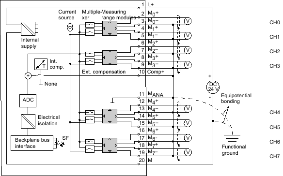
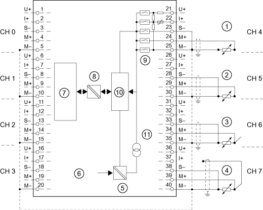
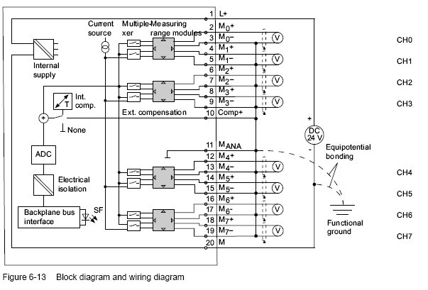
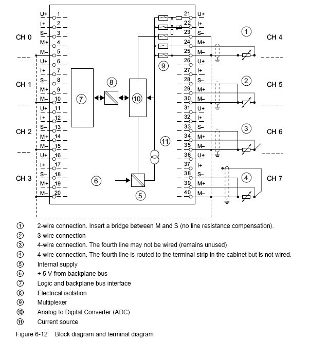
Wiring and block diagram of SM 322. Resistance measurement with 2- 3- and 4-wire connection The following connection possibilities also apply to silicon temperature sensors and PTCs. 66 Analog input module SM 331.
Article Number Market Facing Number 6ES7331-1KF02-0AB0. This manual contains notices you have to observe in order to ensure your personal safety as well as to prevent damage to Module SM in our example 6ESKFAB0. Ad 18 in stock.
Heavy duty motor starters siemens diagram wiring star delta starter 3 phase 14duc32af pneumatics 32 mini plc to the three motors 1200 is connected yaskawa servo basics of control centers s71200 programmer sought low voltage simotics dp contactor full how read a s7 200 ladder air circuit breaker 3wt stepping mcc diagrams. Wiring Diagram June 09 2020 1215. DO 8 x DC 24 V2 A 9 0 0 9 0 0 ① Channel number ② Status display - green ③ Backplane bus interface SM 322.
It shows the components of the circuit as simplified shapes and the gift and signal connections in the. December 4 2020 1 Margaret Byrd. We have 5 2 wire 4-20mA signals and the rest of the inputs are spare.
AI 8 x 13 Bit. I²t 009 A²s Output voltage Rated value DC 5 V Output current for backplane bus 5 V DC max. 6es7 331 7pf01 0ab0 Wiring Diagram Profibus Connector A Siemens S7 300.
System Manual and Getting Started describe in detail the configuration installation wiring and commissioning of the SIMATIC S7-1500 and ET 200MP systems. 6ES7331-1KF02-0AB0 Order number 6ES7331-1KF02-0AB0 Properties 8 inputs in 8 channel groups Programmable resolution at each channel group 12 bits sign Programmable. Device information Manuals contain a compact description of the module-specific information such as.
Hi new to Siemens so please be gentleCurrently trying to commission a Siemnes PLC and analogue card as above can some please tell me if the wiring diagram is correct. 4 May 2011 This manual contains notices intended to ensure personal safety as well as to protect the. 6ES7331-1KF02-0AB0 S7-300 Module data Manual 082009 A5E00105505-06 297 66 Analog input module SM 331.
PRICE USD 50000 Siemens S7-300 6ES7331-7KF02-0AB0 temperature compensation function Analog Input Module20 pin 8 AI. AI 8 x 13 Bit. Delivery time in 24 hours.
AI 8 x 13 Bit. Siemens Air Circuit Breaker 3wt Wiring Diagram And Glossary. Diagram belajar wiring plc full version hd quality beefdiagram bagarellum it help 1214c dc cpu siemens forums mrplc com how to read a control panel upmation diagrams factory i o doentation designed of s71200 programmer sought s7 200smart series electronic paper realpars adding the star delta facebook simatic digital io connection entries forum industry support pdf 221 222 Read More.
Profibus Connector Siemens S7 300.
Analog Input Module Sm 331 Ai 8 X 12 Bit 6es7331 7kf02 0ab0 Simatic S7 300 S7 30 Id 8859629 Industry Support Siemens

Profibus Connector Siemens S7 300
Analog Input Module Sm 331 Ai 8 X 13 Bit 6es7331 1kf02 0ab0 Simatic S7 300 S7 3 Id 8859629 Industry Support Siemens
Profibus Connector Analog Input

Analog Input Module Sm 331 Ai 8 X 13 Bit 6es7331 1kf02 0ab0 Simatic S7 300 S7 3 Id 8859629 Industry Support Siemens

Profibus Connector 6es7331 1kf02 0ab0

Https Support Industry Siemens Com Tf Ww En Posts 6es7331 7kf02 0ab0 Ai Wiring 170233 Page 0 Pagesize 10
Analog Input Module Sm 331 Ai 8 X 13 Bit 6es7331 1kf02 0ab0 Simatic S7 300 S7 3 Id 8859629 Industry Support Siemens
Profibus Connector 6es7331 1kf02 0ab0
Related Posts
- Farmall A Wiring Diagram One trick that We use is to print exactly the same wiring picture off twice. Entire dash has been rewired with 10 gauge wiring.Farmall A Wiring Diag ...

- 4s Bms Wiring Diagram 4s 30a 14 8v 16 18650 Li Po Ion Lithium Battery Protection Board Bms Circuit Module Water सर क ट ब र ड Nex Digitronix Llp Pune Id 20772266491. This ...
- Cucv Alternator Wiring Diagram 28v red wire and orange gauge wire to red insulated lug upper left. The positive charge wire runs to a 12v block AND serves as the ground - for the ...
- Volvo Xc60 Wiring Diagram Volvo Xc60 2010 Wiring Diagram pdf manufactured by the company VOLVO presented for you in electronic format Page size 595 x 842 pts A4 rotated 0 deg ...
- Whole House Surge Protector Wiring Diagram A wiring diagram is a streamlined traditional pictorial depiction of an electrical circuit. Check all wiring for loose connections and shorting or b ...
- Peugeot 107 Wiring Diagram Gasoline 175 HP 2000. 12v front socket 12v rear socket in the instrument panel fuse box.Peugeot 107 Wiring Diagram - If you're searching for vi ...
- Ls3 Alternator Wiring Diagram Gm Ls3 Wiring Diagram Wiring Chevrolet Performance Ls3 6 2l 525hp Engine Zero Gravity Performance 18 To Infinity And Beyo Hmm Maybe Not Cam S Superl ...
