Power to the reader is selectable. 155 3937mm x 12 3048mm x 45 1143mm.
Acm8 Wiring Diagram - If you're searching for picture and video information linked to the keyword you've come to pay a visit to the ideal site. Our website provides you with suggestions for seeing the maximum quality video and image content, hunt and find more informative video articles and images that fit your interests. comprises one of tens of thousands of video collections from various sources, particularly Youtube, therefore we recommend this movie that you see. It is also possible to bring about supporting this site by sharing videos and graphics that you enjoy on this site on your social media accounts such as Facebook and Instagram or educate your closest friends share your experiences about the ease of access to downloads and the information that you get on this site. This site is for them to stop by this site.

Door Access Device With Fire Panel Integeration
Central Bank Of India 100 Years Logo Vector.
Acm8 wiring diagram. ACM8 will trigger all outputs except those that are programmed other wise eg. 12 Vdc VIN must be greater than 20 Vdc or power is passed-through PT from the input voltage of the MR52-S3 TB7-VIN 300 mA maximum per reader port. Must be a reseller to purchase this product.
For reference Im using a cheap Chinese Ethernet motion controller NVEM 5-axis and the TB6600-based HY-DIV268N-5A controllers with 40V600VA drive supply. Any of the eight 8 fuse protected power outputs are selectable to follow power input 1 or input 2. The iSTAR Pro iSTAR Ultra and iSTAR Ultra SE models are also available in space saving rack mount models.
A voltage is then induced in the other coil called the secondary or output coil. If you have enjoyed this video please consider a donation to my Patreon account so I can continue to provide you and my subscribers with the best content I c. Featuring advanced encryption and backup communication paths the iSTAR design is among the industrys most reliable and secure.
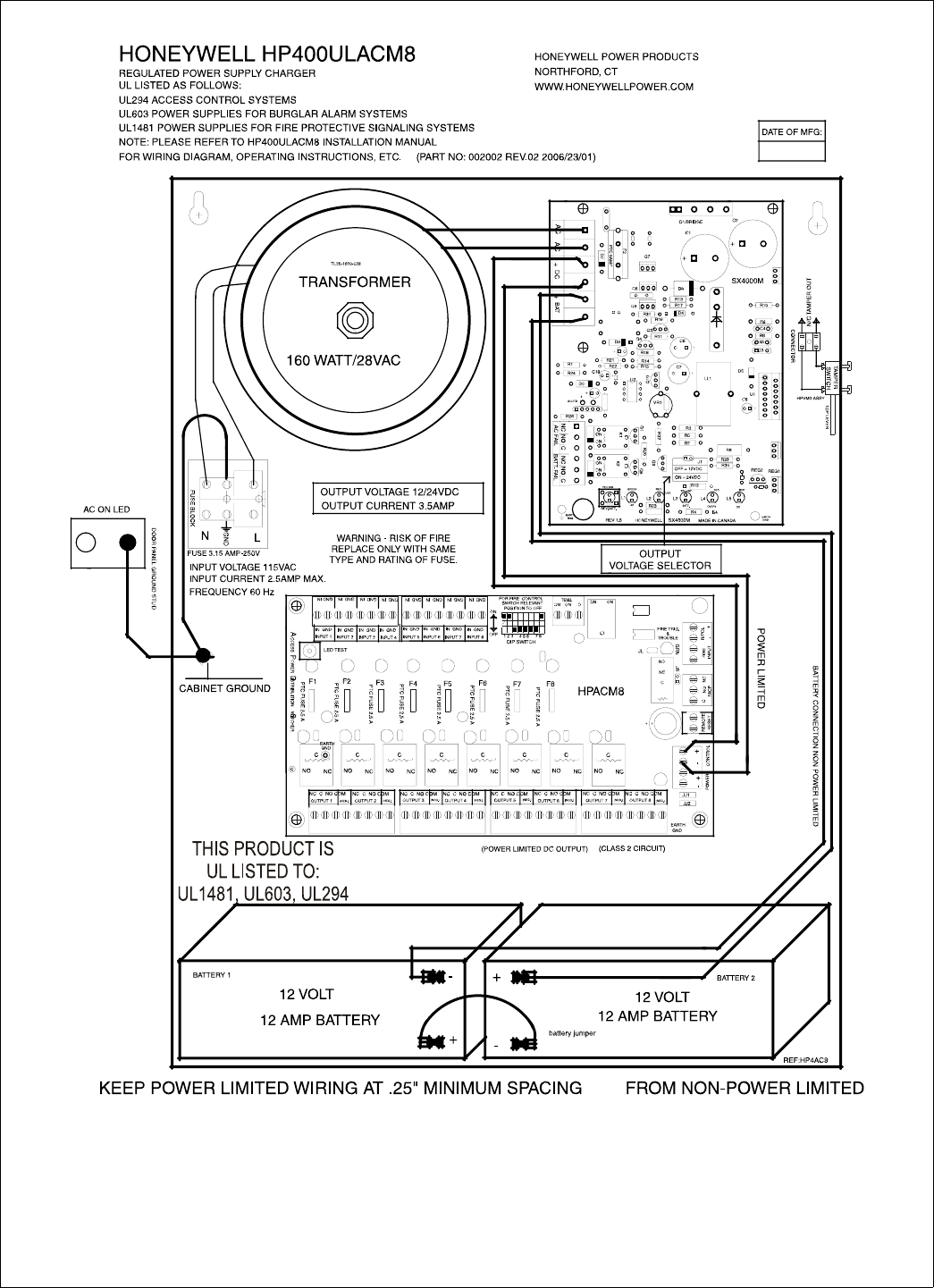
Two or more coils of insulated wire wound on a laminated steel core. Connect the normally open FACP trigger input to the terminals marked INPUT and T on the terminal block labeled FACP INTERFACE. Black Gold Triangles Background.
5VDC to 24VDC up to 10A each or 16VAC to 28VAC up to 14A each. Part of the reason for the rebuild was cosmetic but I was concious that pre. Free Printable Graphic Organizer Template Word.
Panel wiring diagrams and system layout drawings will be supplied by WMU DPS. Input 1 and Input 2 Voltage range. Big Park Company Logo.
Male Underwear Model Transparent Png. ACM8 board main fuse is rated at 10 amp. Ensure that there is a 110 Vac mains socket available for connection to the external 18 Vac transformer.
A Normally open FACP input. Contacts fire alarm disconnect is selectable by output UL R. Data wire will be run between card access panels and between rooms housing access panels.
Lace Pattern Vector Illustrator. A Factory installed power supplies provide common power for both ACM8 boards and all connected access control devices. The change of voltage or voltage ratio between the primary.
Panel in the wiring loop the greater the possibility of compromise of the unprotected loop wiring after the resistor position. Please read through this manual for correct operation. We suggest that after reading it you keep this manual.
Door and window contacts with built-in resistors are the absolute best and easiest way of placing the end of line resistor in that ideal position. Input TMP is used for monitoring cabinet tamper and PFL input is used power failure monitoring. CKM-MR52 Reader Wiring Alarm Contact Wiring Inputs 1 to 8 may be configured to use or not to use End-Of-Line EOL resistors and for normally open or normally closed contacts.
Outputs will operate in both Fail-Safe andor Fail-Secure modes. The suite of iSTAR door controllers provides powerful network-ready solutions for enterprise-wide access control. Green LED on ACM8 board indicates FACP disconnect is triggered.
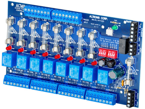
Gift Card V Bucks Codes Free. Outputs are activated by an open collector sink or normally open NO dry trigger input from an Access Control System Card Reader Keypad Push Button PIR etc. For 5 meter pigtail readers PN.
2003 Ford E350 Fuse Box Diagram. The power supply board has limited capacity to power these devices see page 42. OWNERS MANUAL We appreciate your purchase of this main unit.
Outputs 5 thru 8 in the fiftyfifty mode and those outputs wired with Normally closed inputs. Resistors are available in. When voltage is introduced to one coil called the primary it magnetizes the iron core.
These two inputs are for contact closure monitoring only. If necessary ensure that external power supplies are available to power the door-release devices and auxiliary outputs. 9xxxxxLEKxxxxx follow the wiring diagram on the reader.
FACP output relay indicates that FACP input is triggered form C contact rated 1A28VDC not evaluated by UL. Each reader port supports a reader with TTL D1D0 ClockData F2F or 2-wire RS-485 signaling. Acm8 Wiring Diagram.
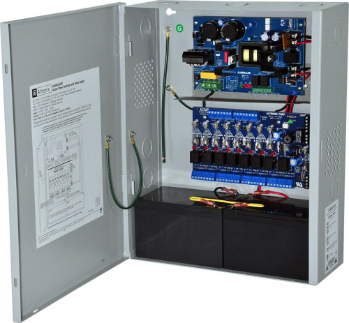
Enclosure accommodates up to two 2 12AH batteries. Any changes must be approved in. 8 Output Access Power Controller Module - Converts one 1 12 to 24 volt AC or DC input into eight 8 fused power outputs individually selectable Fail-Safe Fail-Secure outputs or dry form in.
ACM8 will route power to a variety of access control hardware devices including Mag Locks Electric Strikes Magnetic Door Holders etc. Just search for HY200 2226 0470 the ACM8 just depicts shaft sizesspecial features and doesnt normally make any difference to the basic spec That puts them at 47A coil however you need to know how the motor coils are wired are they 46 or 8 wires to know how to set the drive current. The ACM8ACM8E will provide either eight 8 switched power outputs eight 8 dry form C outputs or any combination of of both switched power and form C outputs plus eight 8 unswitched auxiliary power outputs.
See wiring diagram for accepted device wiring. For better for worse Ive been trying to sort problems with my mill heavily modded Denford Starmill lately rebuilding the control cabinet from scratch. Enclosure Dimensions L x W x H approx.
Power supply input options.
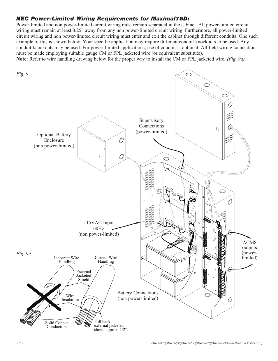
Altronix Maximal77d Installation Instructions User Manual Page 16 20
Altronix Products
Honeywell Power Supply Hp40ulacm4cb Users Manual 52898
Altronix Products

Acm8 Series Ul Listed Sub Assembly Access Power Controllers Installation Guide Pdf Free Download
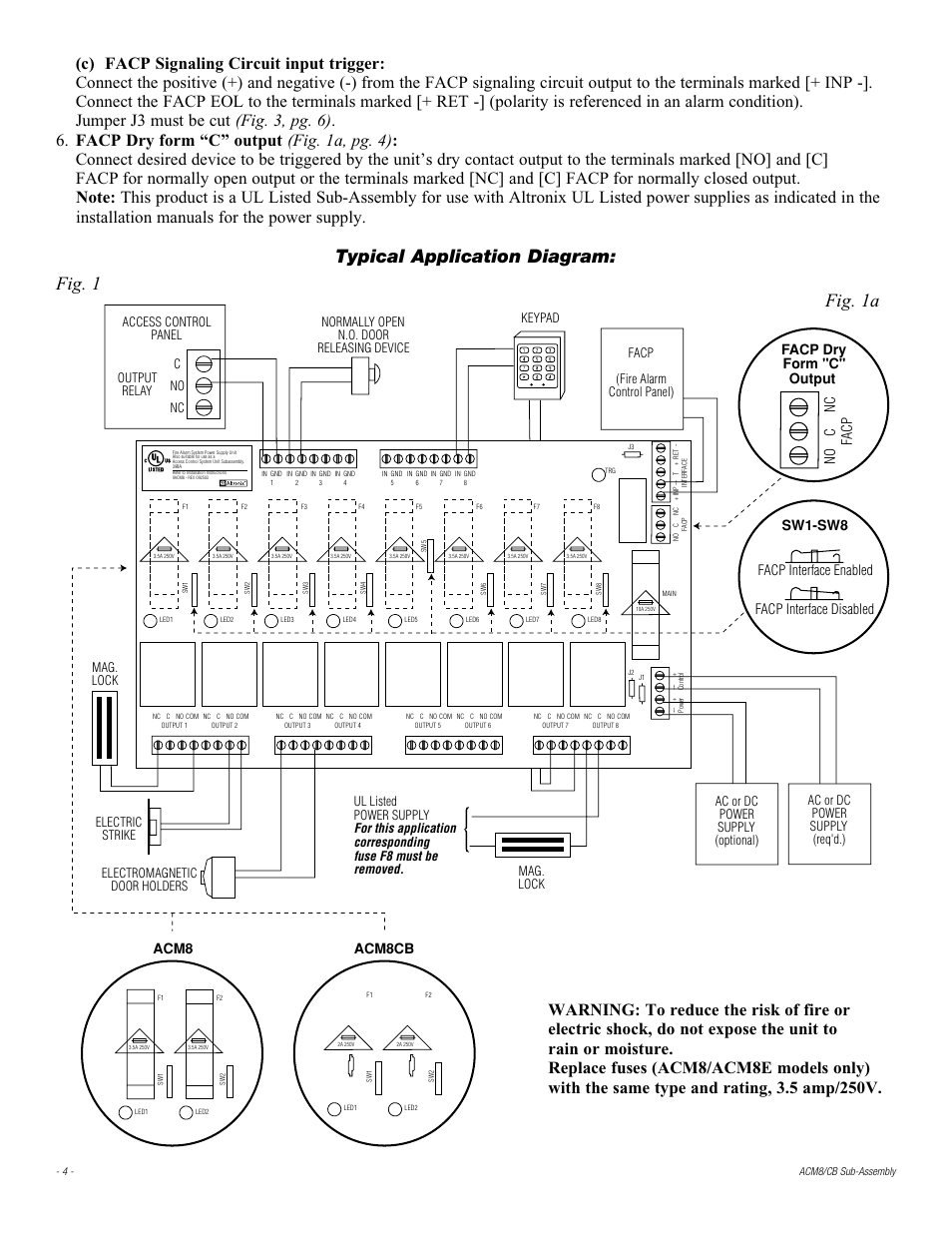
Typical Application Diagram Fig 1 Fig 1a Altronix Acm8cb Installation Instructions User Manual Page 4 8
Https Enconelectronics Com Images Dks Altronix Power Supplies Tb 9 15 Pdf

Altronix Acm8 Installation Manual Pdf Download Manualslib
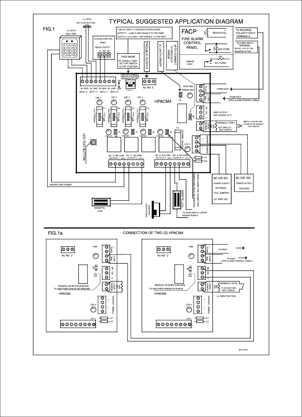
Honeywell Power Supply Hp40ulacm4cb Users Manual 52898
