Boost Leash gear based 1-6 gears. Leash Electronics Home Facebook.
Leash Boost Controller Wiring Diagram - If you're looking for picture and video information linked to the key word you've come to visit the ideal blog. Our site gives you suggestions for seeing the highest quality video and picture content, search and find more informative video content and images that fit your interests. comprises one of tens of thousands of video collections from several sources, particularly Youtube, so we recommend this video that you view. You can also bring about supporting this site by sharing videos and graphics that you like on this blog on your social media accounts such as Facebook and Instagram or educate your closest friends share your experiences about the ease of access to downloads and the information you get on this site. This site is for them to visit this website.

Hand Gesture Controlled Robotic Arm Using Arduino Nano Robot Arm Arduino Hand Gesture
Download full version PDF for Leash Boost Controller Instructions using the link below.
Leash boost controller wiring diagram. Harness wiring kit for Leash Electronics StreeStrip relay board. E-Boost2 2005-current Complete User Manual. AMS-2000 Nitrous Controller Wiring Guide Page 2 PIN COLOR FUNCTION DESCRIPTION 1 RED POWER Swit ched 1 2vdc Main Power Supply Use a 10 amp F use 2 BLACK GROUND - Bat t ery G round 3 ORANGE ERPM Engine RPM T ach Si gnal I nput 4 GREEN DSRPM Drive Shaf t.
Some setups require two solenoids and some require one. BOOST CONTROL PORTION DETAILS. - Refer to the following table and diagram for detail on wiring the e-Boost2.
The writers of Leash Boost Controller Wiring Diagram have made all reasonable attempts to offer latest and precise information and facts for the readers of this publication. Wire Connect to RED 12 Volts switched through ignition connect via 5 Amp fuse supplied. Leash Boost Controller Instructions - Read Leash Boost Controller Instructions PDF on your Android iPhone iPad or PC directly the following PDF file is submitted in 5 Jul 2020 Ebook ID PDF-9LBCI16.
Installing the Holley Dominator EFI - All Wired. E-Boost1 2002-05 Complete User Manual. 12volt ground and launch input.
E-Boost2 2005-current Quickstart Guide. Build is complete all that is left is wiring the boost leash. LEASH BOOST CONTROLLER INSTRUCTIONS PDF.
Current Orders Lead Time. The creators will not be held accountable for any unintentional flaws or omissions that may be found. I may work in ITbut I am an idiot with wiring so any and all help is appreciated.
Youll have to play with the number to learn how much psi it takes on the controller to make the boost you want. When the switch is off the Target Boost should come from the Boost vs. This coronavirus crap is catching up to us now.
The number you set will be psi your putting on the top port. Leash Electronics is here to provide high quality affordable racing electronics to the WORLD. StreetStrip uses of manifold pressure OR co2 pressure for control and it does away with the activation wire and the controller automaticly activates when it senses more that 2psi boost which makes it work VERY well on street cars since its automatic.
Now since its a gate pressure controller you have to understand that the numbers you set in the controller ARE NOT boost. From the controller i. Simple 3 wire hookup.
As you cycle the T-BrakeLaunch switch you should see the Target Boost change. Theyre driven by a Pulse Width Modulated PWM output of the ECU52. If the boost pressure exceeds the wastegate spring pressure the gate valve will begin to open and lower boost.
8 or 11 switch wiring complete kits. Pro 4 Stage Nitrous Timer. Dual Stage Boost Controller.
Dual 70amp Relay Board. Programmable nitrous controller by Leash Electronics allow precise control of various stages of nitrous even when using a transbrake. 9366 likes 10 talking about this 9 were here.
4 Stage Nitrous Timer Original Version. Electronic Boost Controller Product Number. E-Boost STREET 30psi Manual.
EFI Pro IO Module. Zero Function and PIN. I have a boost leash which I have fabbed up a mount for all wires to solenoids run and whatnot.
E-Boost2 2005-current Wiring Diagram. Rs380 Worm Gearbox Universal Children Electric Car Gearbox. FYI All of our controllers are off the website for now due to all our suppliers do not have LCD screens available.
About Press Copyright Contact us Creators Advertise Developers Terms Privacy Policy Safety How YouTube works Test new features. Holley boost control solenoids are designed for optimal performance when using the boost control function of Holley EFI. Beefcake Racing is an Authorized Dealer for Leash Electronics please give us a call 1-855-827-7223 from 9am-10pm EST for pricing and info.
The boost control solenoids NC port always sees boost pressure. Dc 3v 6v To 400kv 400000v Boost Step Up Power Module High Voltage Transformer. Brief overview on the plumbing of a single port boost control solenoid.
Controllers around 4 week. Single Stage Boost Controller. Switch to the data monitor window that has boost related variables.
The parts we use are getting hard to find right now. Choosing An Electronic Boost Controller Here Is A Good Run. When the switch is on the Target Boost should be the Launch Target value.
TS-03011001 to TS 1013. The boost controller should be hooked to the top port of your wastegate. Progresser Nitrous Wiring Diagram For To Wiring Library.
The Boost Leash is a 5 stage time based plus launch stage RaceStreet style boost controller. This unit is very accurate and consistant. Let me explain what it does.
The bottom of the wastegate ALWAYS sees boost pressure. Diagram Edelbrock Nitrous Controller Wiring Diagram For.

Pin On Coe

Pin By Turbo On Wire Custom Relays Setup And Ecm Wiring Diy Car Electronics Diy

Boost Leash Wiring Diagram Delima Guesthouse
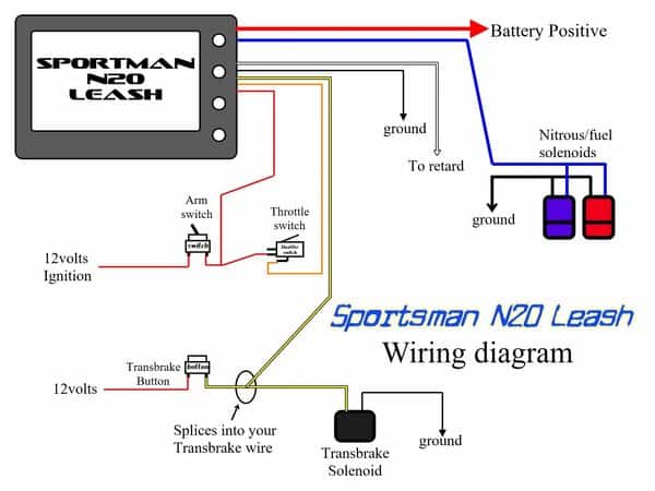
Leash Single Stage Sportsman Nitrous Progressive Controller Ssnp

Engine Ground Diagram Online
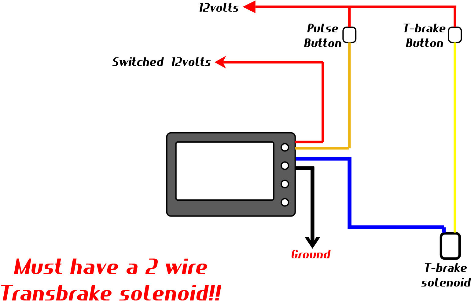
Boost Leash Pulse Leash Combo Unit Hartline Performance

Wiring Diagram Ecu 2kd Ftv Throttle Systems Engineering Wiring Diagram Systems Engineering Ecu

Home Theater Speaker Wiring Diagram Wiring Diagram Access Control System Security Camera Wiring Diagram
Boost Leash Users Please Chime In Svtperformance Com
