I think you are correct about the number of poles in your motor. Wiring Diagram includes numerous in depth illustrations that display the relationship of assorted things.
Yamaha Analog Tachometer Wiring Diagram - If you're searching for picture and video information linked to the key word you have come to pay a visit to the right site. Our site gives you suggestions for seeing the highest quality video and picture content, search and find more enlightening video articles and graphics that fit your interests. includes one of thousands of video collections from several sources, particularly Youtube, so we recommend this movie for you to view. It is also possible to bring about supporting this site by sharing videos and graphics that you like on this site on your social media accounts like Facebook and Instagram or educate your closest friends share your experiences about the simplicity of access to downloads and the information you get on this website. This site is for them to visit this website.

32 Wiring Diagram Ecu Vixion
I am having trouble connecting the gauge to the.
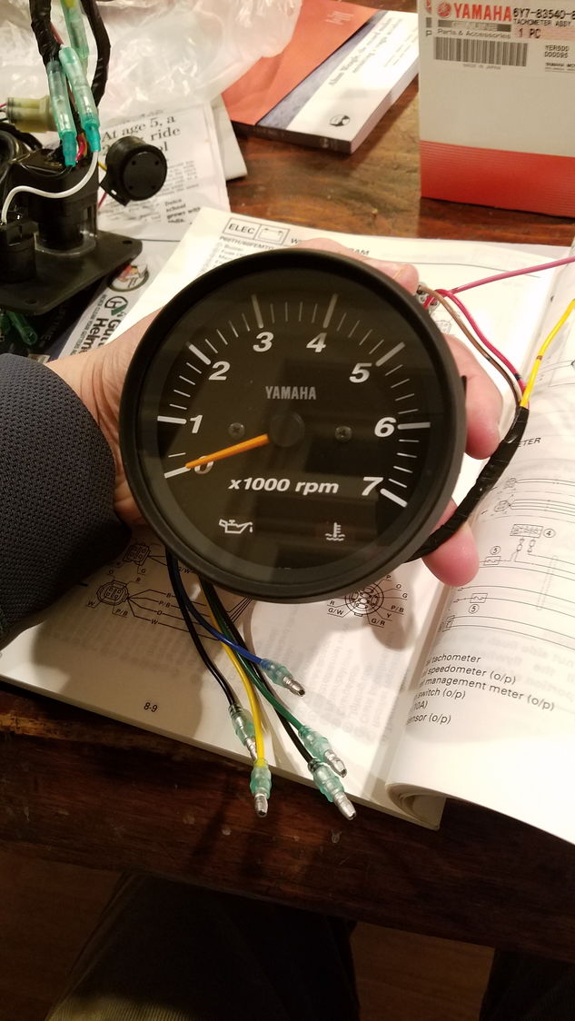
Yamaha analog tachometer wiring diagram. The Yamaha has a 4 pin female plug plus a green wire and a black wire on the upper left looking at the rear of the tach exiting from a potted hole and a black wire and a blue wire exiting from a rubber cover marked N461A whatever that is on the upper right. The yamaha has a 4 pin female plug plus a green wire and a black wire on the upper left looking at the rear of the tach exiting from a potted hole and a black wire and a blue wire exiting from a rubber cover marked. Yamaha analogue tachometer wiring Yellow is for 12 volt positive black is for the ground and green is for the tachometer signal.
Yamaha Outboard Tachometer Wiring Manual E-Books Yamaha Outboard Tachometer Wiring Diagram. Yamaha tachometer wiring help the outboard rigging guides single any gauge magicians converting 2 str to analog rpm not working hull tach a 4 stroke 70hp boat outboards 703 remote conrol box quick question with 6y5 8350t d0 00 install engine instrument made easy linkedin faria gauges including digital nmea 2000 connector in f70la command link kit how aem f on 2018 fxsvho conversion pro series oil light diagram. Hook those three wires up and see what happens.
It shows the components of the circuit as simplified shapes and the knack and signal links together with the devices. How to make it work and fix the problemThe newer Yamaha OEM Multi-Function Digital Tachometer installing and not matching the plug and play wiring from old. For Garcons analog tachometer like the above photo tachometer wiring connections are as below.
The only wires coming out of the oil and temp warning lights that enter the connector are the red w black. Wire color coding Yamaha Tach Gauge. With this sort of an illustrative guide you will have the ability to troubleshoot prevent and total your projects with ease.
Yamaha Outboard Tach Wiring Diagram Tachometer Wiring Diagram Wiring Diagram. Wiring Diagram includes numerous in depth illustrations that display the relationship of assorted things. Yamaha Outboard Tachometer Wiring Manual E-Books Yamaha Outboard Tachometer Wiring Diagram.
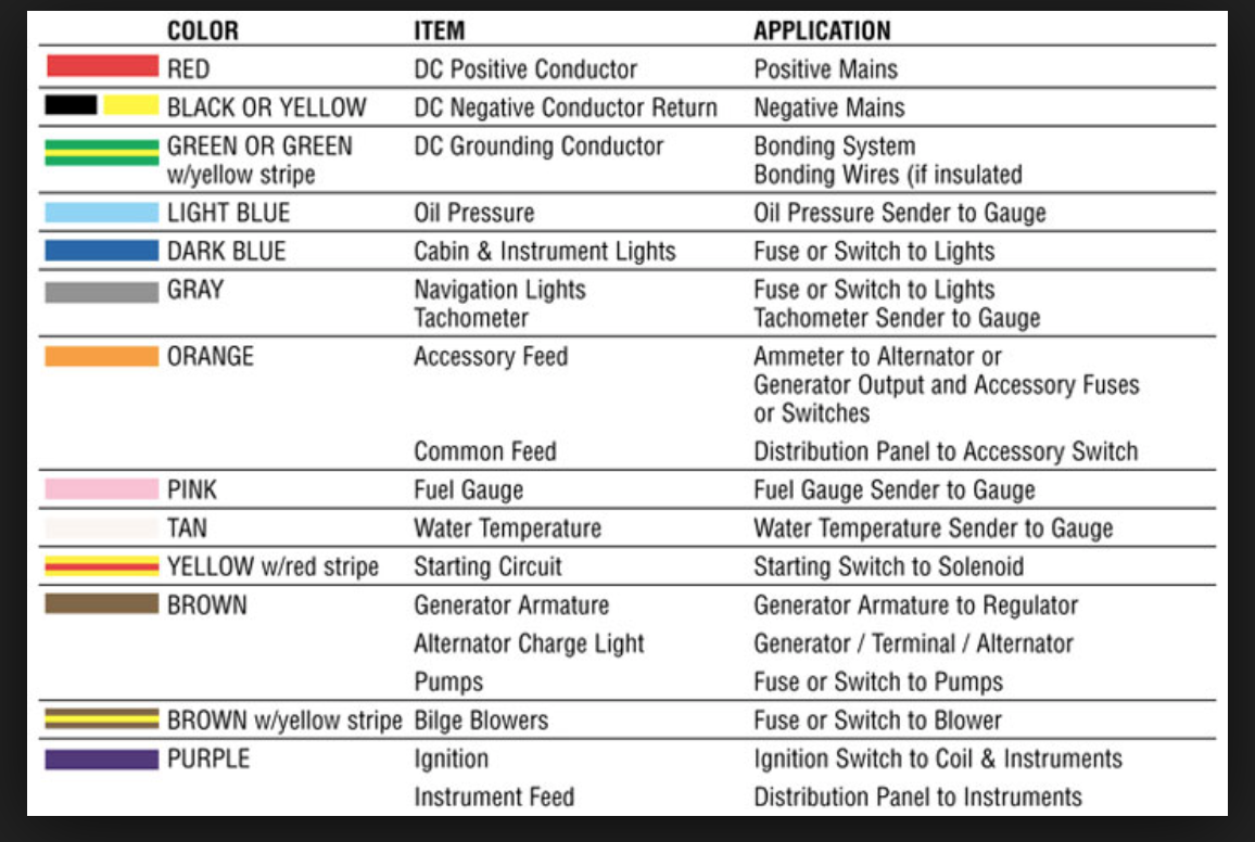
According to that wiring scheme the insulation color GREEN is used for tachometer signals. Yamaha outboard tachometer wiring diagram mercury outboard wiring diagrams mastertech marin rh maxrules 50 HP Mercury Outboard Wiring Diagram Mercury Outboard Wiring Schematic Diagram. I am re powering my boat with a 2005-F90TLR 4 stroke Yamaha.
Yellow wire is connected to ignition switch ON position to connect to positive. It consists of guidelines and diagrams for different kinds of wiring strategies along with other products like lights home windows and so forth. The yamaha has a 4 pin female plug plus a green wire and a black wire on the upper left looking at the rear of the tach exiting from a potted hole and a black wire and a blue wire exiting from a rubber cover marked n461a whatever that.
Yamaha Outboard Wiring Harness Diagram Daily Update Wiring Diagram Wiring Yamaha Analog Tach To 2010 115 4 Stroke Page 1 Iboats Bagikan Artikel ini. June 30 2020 Wiring Diagram by Anna R. Hanya anggota dari blog ini.
Usually with a Yamaha outboard engine the owners manual provides an electrical schematic diagram that identifies all the major components the wiring colors and the signal functions. Wiring Diagram Pics Detail. It consists of guidelines and diagrams for different kinds of wiring strategies along with other products like lights home windows and so forth.
All is good except for connecting the new Yamaha tach assembly gauge 6Y7-83540-80-00. Wiring yamaha analog tach to 2010 115 4 stroke. Yamaha Outboard Tach Wiring Diagram wiring diagram is a simplified satisfactory pictorial representation of an electrical circuit.
Higginbotham yamaha outboard tachometer wiring diagram You will need a comprehensive expert and easy to comprehend Wiring Diagram. The view is looking directly at it from the end. Wiring configuration is different than most Tachometers20150213 200330 About Press Copyright Contact us Creators Advertise Developers Terms Privacy Policy Safety How YouTube.
Bayliner Tachometer Wiring Daily Update Wiring Diagram Yamaha Outboard Tachometer Wiring Diagram On Harley Dash Light 2008 Yamaha 115 Outboard Wiring Diagram Excellent Wiring Diagram Yamaha Gauge Wiring Diagram Wiring Installing And Calibrating An Outboard Tachometer Youtube 0759b Mercury Outboard Tach Wiring Diagram Digital Resources. I have two tachs a Yamaha and a Mercury. Yamaha outboard digital gauges wiring diagram.
Jul 22 2010. Sounds like the tachometer is already configured for a six pole motor. Wiring color codes here is a listing of common color codes for yamaha outboard motors.
Yamaha outboard tachometer wiring diagram. Yamaha outboard wiring diagram pdf Yamaha Outboard Wiring Diagram Awesome tohatsu 30hp Wiring Diagram Free Wiring Diagrams Schematics. Consult that diagram to verify the circuits and wire colors.
Belum ada Komentar untuk Yamaha Boat Wiring Diagram Posting Komentar. I picked up a used Yamaha 10 pin main harness and control assembly from a 2001 boat. Rodbolt Below you will find a sketch of the female blue connector at the tach end of the harness coming from the engine.
Green wire to negative - or body or ground wire.
Yamaha Analog Tachometer Wiring Diagram Electrical Schematic Diagram
Yamaha Outboard Tachometer Wiring Diagram Wiring Site Resource
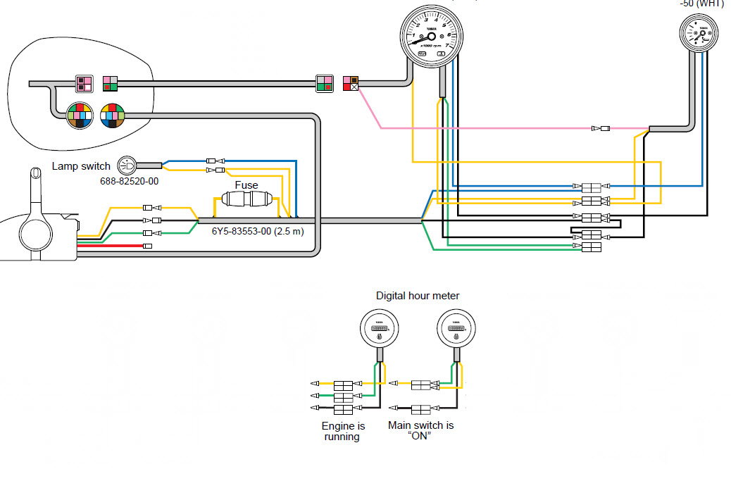
Yamaha Digital Hour Meter Installation Help The Hull Truth Boating And Fishing Forum

Wiring Diagram For My Boat Tachometer
S200 Yammie Saltwater Series Ii Tach Wiring The Hull Truth Boating And Fishing Forum
Yamaha Tachometer Wiring Help The Hull Truth Boating And Fishing Forum
Yamaha Tachometer Wiring Help The Hull Truth Boating And Fishing Forum
Any Yamaha Gauge Wiring Magicians The Hull Truth Boating And Fishing Forum
Yamaha Tachometer Wiring Help The Hull Truth Boating And Fishing Forum
Related Posts
- Peugeot 107 Wiring Diagram Gasoline 175 HP 2000. 12v front socket 12v rear socket in the instrument panel fuse box.Peugeot 107 Wiring Diagram - If you're searching for vi ...

- Plc Analog Input Wiring Diagram The UK1F-E7-0A is an 18mm diameter sensor that has a PNP NONC. Control unit allen bradley slc 500 installation instructions manual analog input modu ...
- Clearwater Lights Wiring Diagram Virtual Clearwater Lights Simulator. Chevy tail light wiring.Clearwater Lights Wiring Diagram - If you're searching for video and picture infor ...
- Vrx755vd Wiring Diagram Jul 4 Learn to draw the Lewis structure of HCN understand molecular geometry This is how Lewis dot structure of Hydrogen Cyanide goes. Here is a pic ...
- Paradox Alarm System Wiring Diagram Quick User Guide for Paradox Spectra SP Series SYSTEM MASTER CODE 1234 1 How to ARM the alarm system a How to do REGULAR ARMING the alarm system Hol ...
- Cucv Alternator Wiring Diagram 28v red wire and orange gauge wire to red insulated lug upper left. The positive charge wire runs to a 12v block AND serves as the ground - for the ...
- Volvo Xc60 Wiring Diagram Volvo Xc60 2010 Wiring Diagram pdf manufactured by the company VOLVO presented for you in electronic format Page size 595 x 842 pts A4 rotated 0 deg ...
