Connect conduit and make wiring connections at switch terminals. Cap-Level IIA 4-20mA Two Wire Continuous Capacitance Level Sensor NEW F78MP Series Air Radar Continuous Self-Contained Level Sensor FM78MP Rock Crusher Video.
Bindicator Wiring Diagram - If you're searching for picture and video information related to the keyword you've come to visit the right site. Our website provides you with suggestions for viewing the maximum quality video and image content, hunt and find more enlightening video articles and graphics that match your interests. includes one of tens of thousands of video collections from various sources, especially Youtube, so we recommend this video that you see. This blog is for them to visit this site.
Http Www Cabriggs Com Pdfs Pdf Bindicator Bindicatorpointlevel Pdf
BMRX Wiring 22 Input Power and Field Wiring The BMRX is available in AC and DC Models.
Bindicator wiring diagram. Screw cover to housing securely to prevent damage or moisture. General Application Data Sheet. Wiring for Multiple Unit-To-Remote Display Figure 2.
Zero position Wiring diagram To assemble the key must be at the zero position the symbol 0 is at the top and on the terminal block the circuit diagram is uppermost. NCR-80 Operating Instructions - Four-Wire. REPLACEMENT PARTS PART NUMBER DESCRIPTION LAG110760 Micro Switch Assembly LAG110800 Cam Assembly.
Bindicator is a full service supplier of point and continuous level sensors for industrial applications. Ultrasonic Application Data Sheet. The 3-circuit configuration provides the user with the SPDT motor switch and an isolated DPDT switch for control outputs.
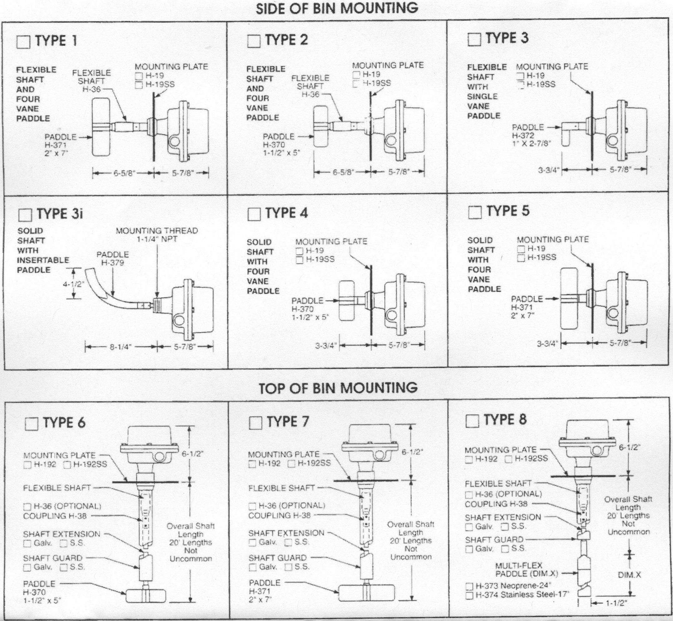
Insert the gasket between the vessel wall and the flange of the unit with the conduit entry facing downward. Mechanicalswiring diagram dimensions are shown in inches with millimeter equivalent in brackets ordering informa tion x model ka kax approvals 1 ulcsace 2 atexiecex 1 x x x operating voltage 0 115vac 1 240vac 3 1224vdc 8 24vac 9 48vac circuit configurationsprocess connection 1 2 circuits 2 spdt1-14 npt. BINDICATOR Installation Operation Maintenance Manual LBY280183 4 15 Technical Specifications GP-4 SENSOR Power Requirements 120 VAC or 240 VAC Power Consumption Quiescent.
Non-Contact Liquid Level Bin-Dicator control is a low cost floatless pressure sensitive diaphragm actuated switch that automates the filling and emptying of containers. Do not modify any factory wiring. NCR-80 Operating Instructions - Two-Wire.
Typical Wiring Diagram VI. 120 VAC 10 5060 Hz 32 Watts with heater add 10 Watts to above. TDR-2000 Application Data Sheet.
The AC Models are available to be pow-ered from 24 VAC 115 VAC or 230 VAC 5060 Hz supply voltages. The switch is mounted in a fascia or control panel in three steps. Fasten the unit to the vessel wall with 1 4 in.
3 W DC Power Consumption - ADVANCED 4 W AC. Bolts or cap screws. The DC Models are available to be powered from 12 VDC or 24 VDC supply voltages.
ELECTRICAL INSTALLATION GENERAL SAFETY When using electrical equipment you should always follow basic safety precautions including the following. 3 W DC Power Consumption - ADVANCED 4 W AC. 4 W DC Fuse Fast Blow 1 A 300 V Not User Serviceable Operating Temperature Electronics -40 to 158 F -40 to 70 C.
The installation and wiring of this product must comply with all national federal state municipal and local codes that apply. The actuated switch requires 5 of head pressure on the riser for actuation. SET-UP 11 Lines of.
MP Series Radar Applications Data Sheet. Detach terminal block as in drawing remove fixing nut 2. Durable trouble-free performance is assured because none of the few.
The installation and wiring of this product must comply with all national federal state municipal and local codes that apply. Properly ground the enclosure to an adequate earth ground. 4 W DC Fuse Fast Blow 1A 300 VAC Not User Serviceable Operating Temperature Electronics -40 to 158 F -40 to 70 C.
NCR-80 Operating Instructions - Modbus Levelmaster Protocol. Single Unit-To-Remote Display Wiring VI. MAINTENANCE No scheduled preventative maintenance is required when unit is properly applied and installed correctly.
120 VAC 10 5060 Hz 4 Watts with power to remote display Operating. Board Layout Figure 4. Since 1936 our bin level indicators have been preventing overflow spills controlling surge bins detecting plugged chutes and providing onoff control of pumps and conveyors in the dry bulk industry.
The most popular 2-circuit design contains the motor SPDT switch and a second SPDT isolated switch for control outputs See wiring diagram for illustration. 80 GHz Non-Contact Radar for Solids. 80 GHz Non-Contact Radar for Solids.
Connections should only be made to the terminals described in this section. There is no cleaning required for the unit before or during installation. See the voltage rating on the nameplate for the appropriate supply voltage.
Bindicator Application Data Sheet. Insert switch from front side in fasciacontrol. Board Layout - Sensor Address Location Figure 3.
Original Roto Bindicator Samson Engineering Machinery Co
Https Www Specialtyproducttechnologies Com Docs Default Source Manuals Bindicator Vrf 1000r Installation Operation Manual Pdf Sfvrsn 5
Http Literature Puertoricosupplier Com 084 Bt83742 Pdf

Do You Know The Operation Of Rotary Paddle Level Switch Youtube
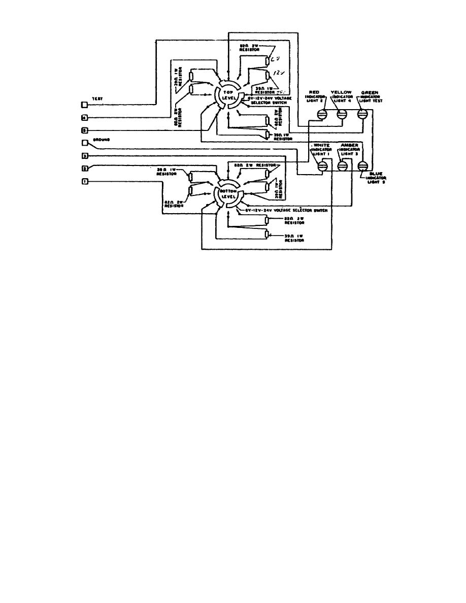
Figure 11 Circuit Analyzer Schematic Wiring Diagram
Https Www Specialtyproducttechnologies Com Docs Default Source Manuals Bindicator Vrf 1000r Installation Operation Manual Pdf Sfvrsn 5

Wire A Rotary Level Indicator To A Light Youtube

510 Headlamp Relay Upgrade Wiring Electrical Ratsun Forums
Https Www Specialtyproducttechnologies Com Docs Default Source Manuals Bindicator Lp 100 200 Installation Operation Manual Pdf Sfvrsn 5
