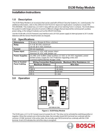
30 Wiring 31 Power Remote Input Door Contacts and Tamper Refer to Table 1 to wire the detector. You can mount the DS150i on the ceiling or wall and aim andor mask its pattern for more effective use based on installation needs.
Bosch Ds150i Wiring Diagram - If you're searching for video and picture information linked to the key word you have come to pay a visit to the right site. Our website gives you suggestions for viewing the highest quality video and image content, search and locate more informative video articles and graphics that fit your interests. comprises one of tens of thousands of video collections from several sources, particularly Youtube, so we recommend this video that you see. It is also possible to bring about supporting this site by sharing videos and images that you like on this site on your social networking accounts like Facebook and Instagram or educate your closest friends share your experiences about the simplicity of access to downloads and the information you get on this website. This blog is for them to stop by this site.

Bosch Ds150i Manual Manualzz
The DS150i is.

Bosch ds150i wiring diagram. Wiring Connector Plug on Circuit Board Figure B. Bosch D8125INV wireless Interface Module. Trim plate for DS151 and DS161 black.
Loosely mount the back cover to the mounting surface using the supplied mounting screws. The voltage must be. DS160 - BOSCH SECURITY SYSTEMS - Anixter.
Connector to Plug Orientation Coil excess wiring behind the back cover along the channels provided. GRI 29-A-W Surface Mount Switch Set 180-12-W Steel Door Switch Set. Page 2 It deactivates when the latch time ends even if motion is still present.
BOSCH DS150i Motion Detector DS151i Motion Detector DS150i PIR DS151i PIR. Bosch D2212B where network connectivity is not available by approval only. Stanley EL series wireless locksets with access control.
Connect to the positive side of the power supply. You can mount the DS150i on the ceiling or wall and aim andor mask its Wiring pattern for more effective use based on installation needs. Summary of Contents for Bosch DS936 Page 1 The DS936 is designed to be surface mounted directly on the ceiling or recess mounted to any 3 12 inch 889 mm standard octagonal box.
2011 Bosch Security Systems. These cookies are used to collect information about how you interact with our website and allow us to remember you. These settings assume the relay timing resets with each trigger set for fail safe PowerNet PowerNet RC.
Bosch D7412GV2 for systems up to 80 zones. The system shall have the ability to. Request-to-exit sensor black sounder.
In this video we outline some basic principles to optimize your detectors performance. BOSCH SECURITY VIDEO DS150I Motion Sensor NA We provide video guidedetail wire diagramso you can easily setup system also provide live help until all working well for you. ŁTroubleshooting Handbook For Truck Mounted Cranes.
Color will be determined by the door color. Manitowoc Boom Trucks Inc. See wiring diagram for accepted device wiring.
Where should you mount your detectors. Aim the detector for the desired coverage. We only do quality product and service because this is.
Wiring for non-spike protected inductive loads. The voltage must be between 12 VAC and 30 VAC or DC. When operating an inductive load that is not spike-protected wire as shown in Figure C.
DS150i Relay Contact Inductive Load Coil KBL005 Bridge Rectifier Coil. 512 942-3000 Sales Fax. Not designed as the primary means of exit for emergency egress.
Motion detector request-to-exits REX will be Bosch DS150i white or DS151I black. Trim plate for DS150 and DS160. Bosch DS150i and DS151i The DS150i in grey and the DS151i in black is a reliable long-lasting REX for standard doors.
Bosch D9412GV2 for systems up to 246 zones. 7600004-003A A CompanyOctober 2001. Bosch D7212GV2 for systems from 1 to 40 zones.
Connect to the positive side of the power supply. A light gray trim plate used when mounting the detector over a standard single-gang box. This website uses cookies.
This setting works best when used with an access control system. PAT LMI MANUAL - DS150. Installation Instructions DS936 Ceiling Mount Passive Infrared Select a location that is most likely to intercept an intruder moving beneath and Intrusion.
The DS150i is available in a light grey DS150i or a black DS151i enclosure. As Bosch DS150i Exit Button Such as Securitron EEB2 2 Red Isonas In Magnetic Lock Black Other wires isolated and taped off Connect Blue to Black When No Door Contact is Used DIP Switch Settings for DS150i Motion and Exit Button Note. To find out more about our.
Bosch DS160 and DS161 The DS160 in grey and the DS161 in black is an ideal solution for doors with gaps such as glass and architectural doors. The relay can also be programmed to fail safe or fail secure during a power loss. For surface wiring use the break out wiring entrance on the front cover at the same end as the wire entrance.
This website stores cookies on your computer. Mount the detector module to the back cover. Panel wiring diagrams and system layout drawings will be supplied by WMU DPS.
Terminal Labels and Descriptions Label Description - Connect to the negative side of the power supply. Austin Ave Georgetown TX 78627-1609. Wireless equipment for 9000 series control panels.
Wire Terminals Sounder Sounder Volume Control DIP Switches Tamper Switch LED Lens Lock-Down Screw IMPORTANT 40 Wiring 41 Power Remote Input Door Contacts and Tamper - Connect to the negative side of the power supply. Bosch TriTech detectors raise the bar when it comes to intrusion detection and deliver excellent catch performance while creating fewer false alarms under a variety of environmental conditions. 512 942-3000 Service Fax.
It comes with a form C relay that can be programmed to latch for up to 60 seconds. Coil excess wiring behind the back cover along the. In order to provide consistent and accurate detection they feature dual motion technology - a combination of PIR and microwave Doppler radar technologies with advanced signal processing.

B O S C H D S 1 5 0 I W I R I N G Zonealarm Results

Bosch Ds150i Manual

Bosch Ds150i Installation Guide
B O S C H D S 1 5 0 I W I R I N G Zonealarm Results

Bosch Ds150i Installation Guide

Bosch Ds150i Installation Guide
Bosch Ds150i Electric Motion Sensor White Youtube

B O S C H D S 1 5 0 I W I R I N G Zonealarm Results
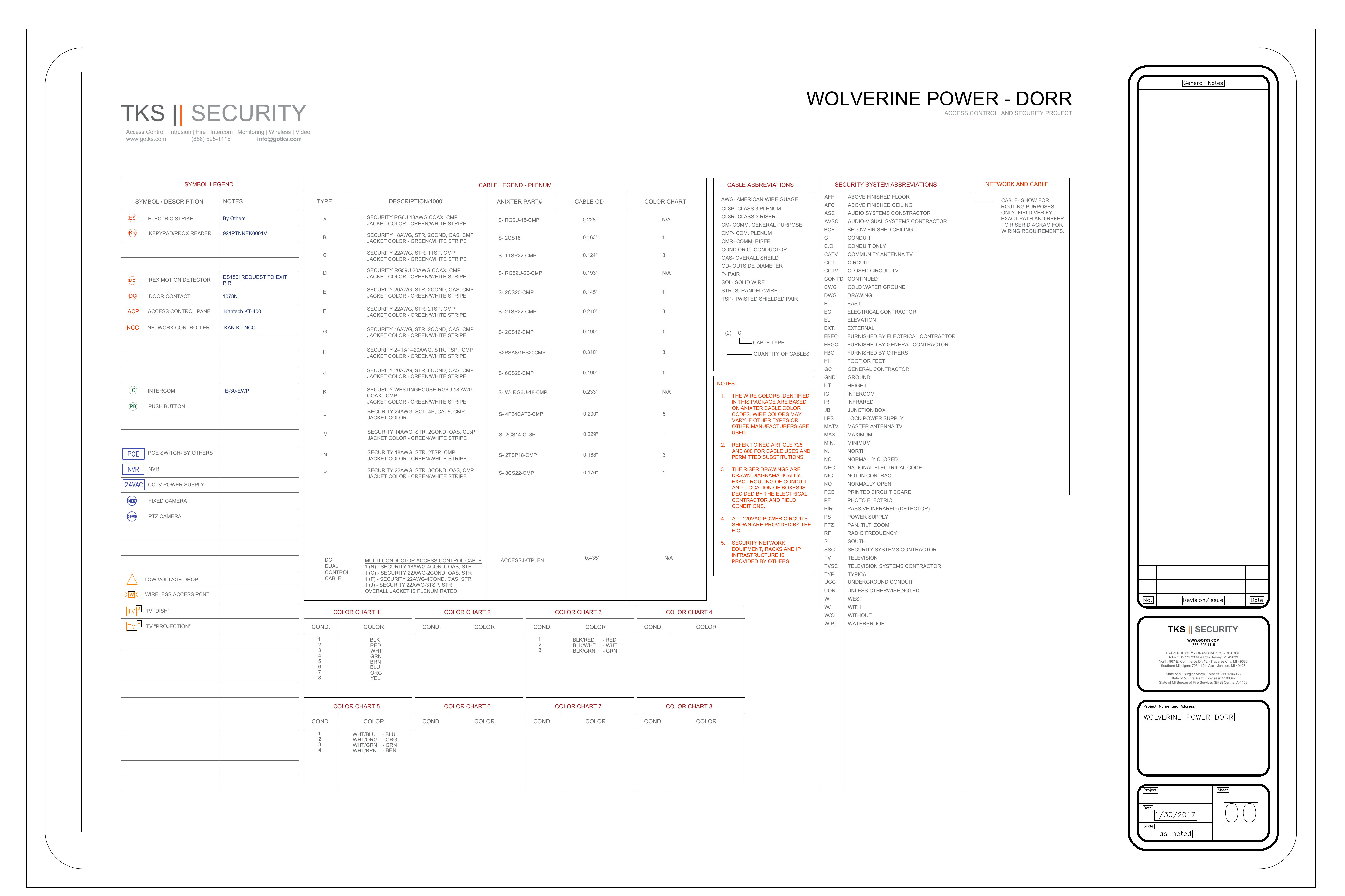
Tks Security Manualzz
