To change patterns momentarily connect. Feniex Fusion Surface Mount Wiring Diagram.
Feniex Fusion Wiring Diagram - If you're searching for video and picture information linked to the key word you've come to pay a visit to the ideal blog. Our site gives you suggestions for viewing the maximum quality video and picture content, hunt and find more informative video articles and images that fit your interests. comprises one of thousands of movie collections from several sources, especially Youtube, so we recommend this video that you view. This site is for them to visit this site.

Feniex Fusion Fsm 180 Series Instruction Manual Pdf Download Manualslib
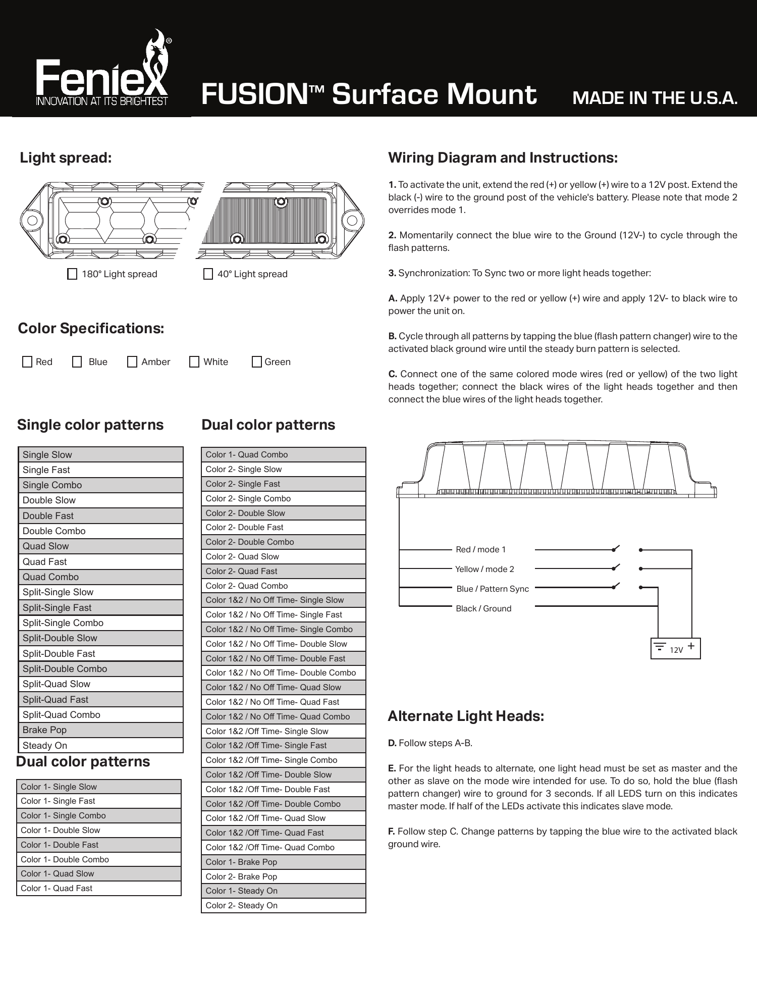
Black 12V - Red 12V Mode 1 Blue PatternSync Yellow Mode 2 Please Note.
Feniex fusion wiring diagram. It shows the elements of the circuit as streamlined forms and the power and signal connections between the devices. Black 12V - Red 12V White Takedown Yellow Flash Mode Green Takedown Flash Blue Left Arrow Gray Right Arrow Brown Mode 1 GrayBlue Center Out Dual Color Fusion. Black 12V - Red 12V White Flood Yellow Flash Mode Green Mode Two Blue Left Arrow.
Black 12V - Red 12V White Flood Yellow Flash Mode Green Mode Two Blue Left Arrow. Fisher Plow Wiring Diagram Minute Mount 2. Black 12V - Red 12V White Flood Yellow Flash Mode Green Mode Two Blue Left Arrow Gray Right Arrow Brown Mode One.
Controller Feniex Mini Instruction Manual. The Fusion 200 features four wires. Red 12V Black 12V- Yellow.
Feniex released a video on the Mini today. Quad 44 Lightbar Instruction Manual. Welcome to the era of automation.
Feniex released a video on the Mini today. Geo Series 14 Mini Lightbar Instruction Manual. Featuring an ARM A9 Quad Core Processor a built-in 200W siren an integrated GPS timing chip an ant-glare LCD screen displaying live vehicle health alerts and much more the Feniex ONE is truly a.
1 To activate the unit extend the red or yellow wire to a 12V post. Mode 2 overrides mode 1 and mode 3 overrides mode 2 and 1. Wiring Diagram 1 3 5 Programming Instructions.
Fusion GPL 49 Lightbar Instruction Manual. WIRING DIAGRAM 2 Momentarily connect the blue wire to the ground 12V- to cycle through the flash patterns. Set up there is a constant switch for wail yelp and a momentary for manual airhorn.
1 programmable mode Directional Patterns Takedown or Work-Light Available Colors. 1994 Ford F150 Front Suspension Diagram. Feniex FUSION Interior Light Bar.
Please note that mode 2 overrides mode 1. Red 12V Black 12V- Yellow 12V and Blue Flash Pattern Changer. Extend the black - wire to the ground post of the vehicles battery.
Geo Series 60 Lightbar Instruction Manual. FUSION Surface Mount MADE IN THE USA. Add a 60Amp Intelligent design 7 pages.
THE FENIEX ONE IS HERE. R B A W G Rugged sheet metal housing. Extend the black - wire to the ground post of the vehicles battery.
Feniex C Manual Online. Feniex Mini Manual Online. Press the OnOff button.
STOPTAILTURN WORK LIGHTS Wire Color Function Polarity Description Black Tail Lights 12v Steady Burn of both tail lights 10 Brightness Red Work Lights 12v Steady Burn GreenWhite Left BrakeTurn 12v Overrides Tail Light BlueWhite Right BrakeTurn 12v Overrides Tail Light WIRING DIAGRAM. For example in case a module will be powered up and it sends out a new signal of 50 percent the voltage and the technician does not know. Black 12V - Red 12V White Takedown Yellow Flash Mode Green Takedown Flash Blue Left Arrow Gray Right Arrow Brown Mode 1 GrayBlue Center Out Dual Color Fusion.
2011 Ford Fusion Wiring Diagram. Wiring Diagram Single Color Fusion. The Fusion 100 features four wires.
1 Setting button as momentary. Feniex Instruction Manual Directory. Black 12V - Black 12V - Red 12V Mode 1 Red 12V Mode 1 White Mode 2 Green PatternSync 12V - Fusion 200 Wiring Please Note.
This video explains how to wire your Feniex Fusion GPL Light Bar using the datalinkThe Feniex Fusion 49 GPL Exterior Light Bar Dual Color is big bright a. Diagrams for the following systems are included. Fusion 60 Lightbar Instruction Manual.
This video demonstrates the Ford Fusion Complete Wiring Diagrams and details of the wiring harness. 1995 Ford F150 Front Suspension Diagram. To activate the unit extend the red or yellow wire to a 12V post.
Ford fusion wire diagram. 2007 ford fusion wiring diagram wiring diagram is a simplified within acceptable limits pictorial representation of an electrical circuit. To properly read a cabling diagram one has to find out how the particular components in the method operate.
Posts Related to Ford 8n Wiring Diagram Front Mount. Fusion Mini Lightbar Instruction Manual. Ford F250 4x4 Front Hub Assembly Diagram.
Each unit mounts to existing visor brackets 16 flash patterns for single color Capabilities. WIRING DIAGRAM Note. Ford F150 Front Axle Diagram.
Black 12V - Red 12V White Takedown Yellow Flash Mode Green Takedown Flash Blue Left Arrow Gray Right Arrow Brown Mode 1 GrayBlue Center Out Dual Color Fusion. To activate the unitextend the. 19 available vehicle models 180 or 40 light spread optics per module.
Wiring Diagram and Instructions. Mode 2 overrides mode 1. Geo Series 49 Lightbar Instruction Manual.
Diagrams for the following systems are included. Set up there is a constant switch for wail yelp and a.

Feniex Fusion Instruction Manual Pdf Download Manualslib
Https Www Buckeyeevp Com Uploads 6 0 2 5 60255599 Feniex Fusion Light Stick Manual Pdf
Fusion Surface Mount Indd Manualzz
Quad Surface Mount Light
Https Www Feniex Com Uploads Products Media Quad Surface Mount Manual 2 6vof4 Pdf
Feniex L 4910 Instruction Manual Pdf Download Manualslib

Feniex 4200 Controller Fire Department Lights Lights And Sirens Police Lights

Fusion Surface Mount Light
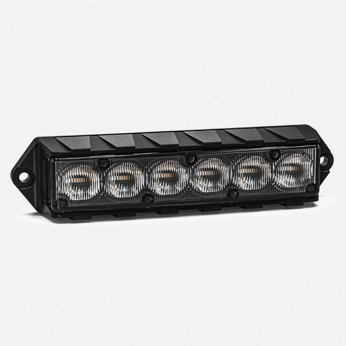
Fusion Surface Mount Light
