Anon - oaadurv. 3510amp supplies power to interior lamp relay on BKLG wire pin 12.
Firelite Miniscan 112 Wiring Diagram - If you're looking for picture and video information linked to the key word you have come to visit the ideal site. Our website provides you with hints for seeing the highest quality video and image content, hunt and find more informative video content and images that fit your interests. includes one of tens of thousands of video collections from various sources, especially Youtube, therefore we recommend this video that you see. This site is for them to stop by this website.
Miniscan 112 1241
Fire-lite tm or equivalent central alarm rel.

Firelite miniscan 112 wiring diagram. MINISCAN 424 Instruction Manual. View online Manual for Fire-Lite MS-9200UDLS Smoke Alarm or simply click Download button to examine the Fire-Lite MS-9200UDLS guidelines offline on your desktop or laptop computer. 4510 amp supplies power in the start or run postion on the RDYE wire pin 20 of cluster.
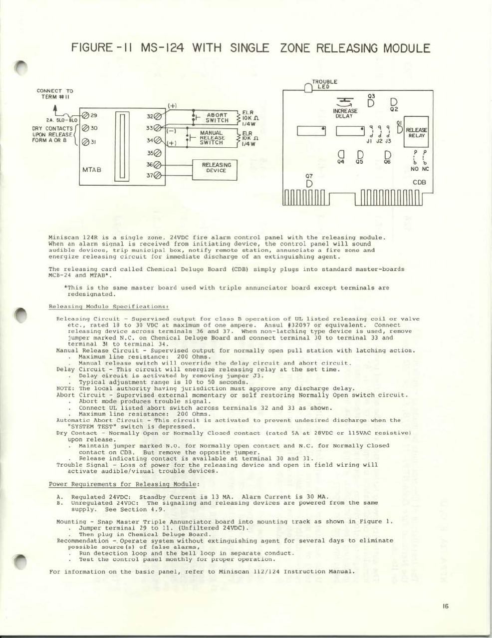
Miniscan 112 124 instruction manual issue number rev. MRP-4424E Agent Release Control Panel. Fire Lite Device Compatibility Document 15384.
6 15586 Rev E 51493 PN 15586E. Conventional Fire Alarm Control Panels Fire-Lite Miniscan 112-124. You can now invite others to collaborate on your content.
112 116 119 125 129 132 138 142 Section Two. Â Two-wire smoke detector compatible. Interior fuse panel fuse no.
H350R Addressable Thermal Sensor. This version of Fire-Lite MS-9600LS Manual compatible with such list of devices as. Â 12- or 24-volt models.
MRP-2002 E MS-2410B Conventional Fire Alarm Control Panel. Contents Components of voice alarm systems - loudspeakers Components using radio links Carbon monoxide detectors - point detectors. Addressable Detectors Modules.
 Meets the requirements of NFPA 72-1993 EditionLocal and. The required group address is set in accordance with the following table. The Fire-Lite MCB-104 is the Master Control Board for the Miniscan 424 Fire Alarm Control Panel 4-zone conventional facp.
Addressable Detectors Modules. MS-9600 CE Addressable Fire Alarm Control Panel. Fire-Lite MS-9050UDC User Manual Operation users manual 216 pages Fire-Lite CHG-120F Installation Operating Manual Installation operating manual 28 pages Fire-Lite Keltron 95M3158 TTM-RPS Wiring Diagram Wiring diagram 1 pages Fire-Lite LCD-80F Manual Manual 36 pages.
Keltron Transmitter Receiever Wiring Diagram Fire-Lite MS- 2410B. 2 Firmware Version 4. Â Low current drain of panel minimizes battery ampere-hour.
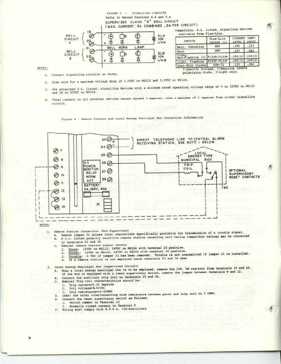
Remote Station Connection 53046. We service all areas of Connecticut and Westchester and Putnam Counties in New York. Str of 25 and 26.
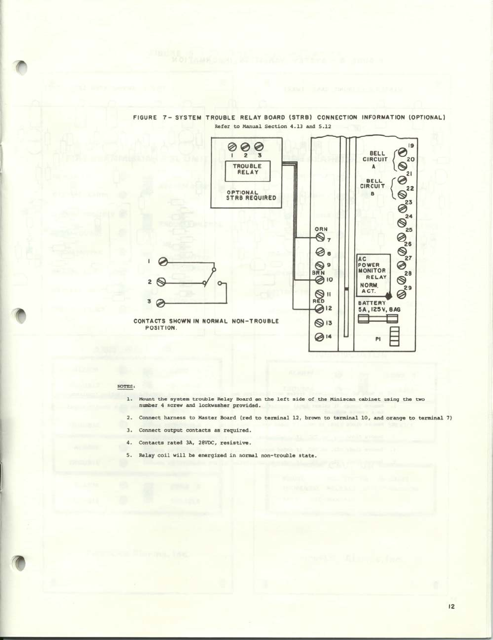
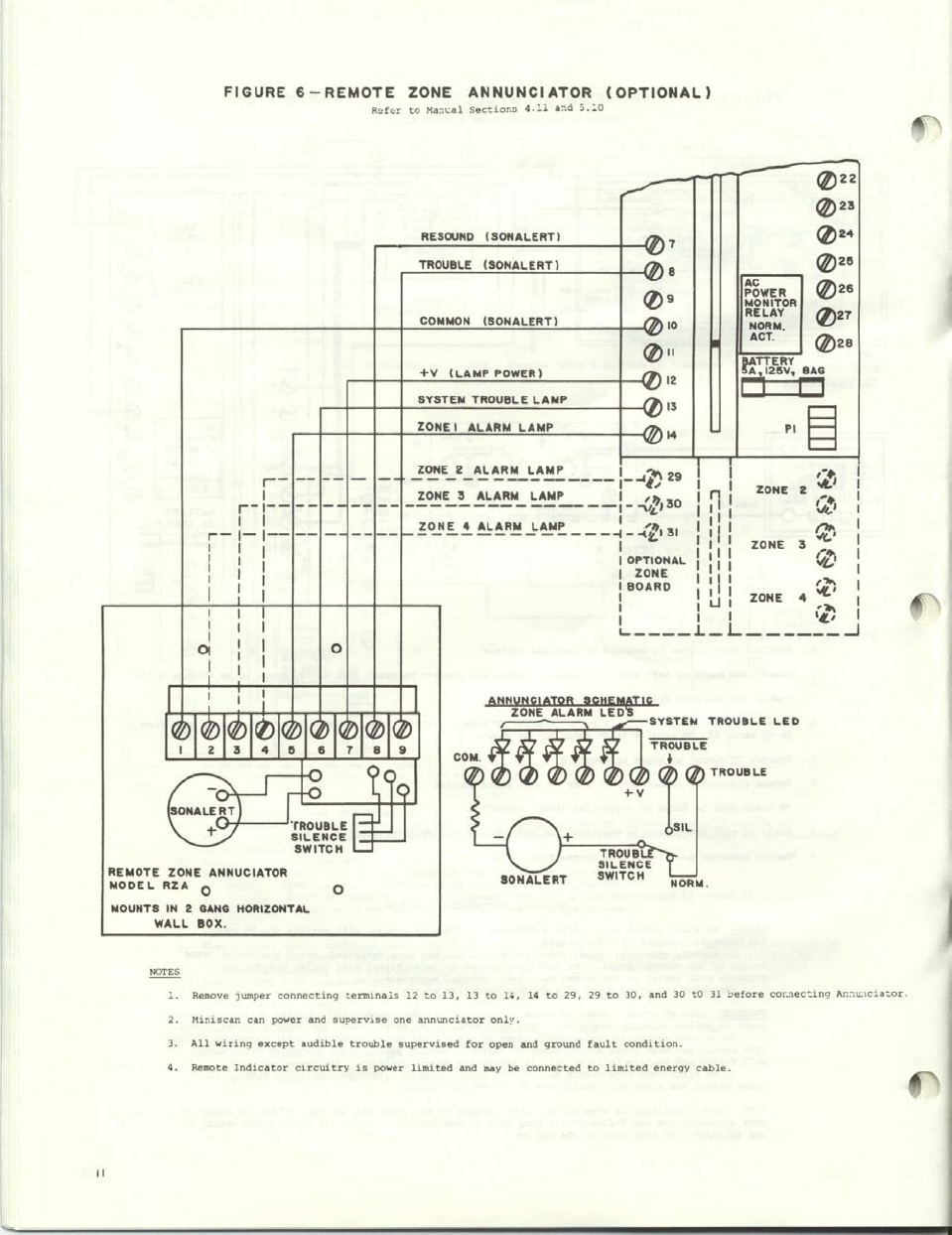
3A Zone Wiring 10 3B Dress Panel Terminal Guide 11 3C Indicating Circuit Wiring Diagram 11 3D Typical End of Line Relay Connection 12 3E AC Connections 12 3F Battery and Meter Connections 13 3G Remote Zone Annunciator Installation 14. Portable fire extinguisher and fire suppression systems sales and service. TransmitterReceiver Wiring Diagram 52071.
Interior fuse panel fuse no. Sensitivity Synchronizations Supplement 51583. Fire-Lite Fire-Lite MS-5024 Replacement board 49935.
Interior fuse box fuse no. Remote Station  Integral battery charger. BRKT-9600 Mounting Bracket 51458.
Please refer to the detector compatibility list in the wiring diagram for specific compatibility questions. Manual 51335 Engineering Specification. DIL switch DIL switch DIL switch setting setting setting addr 1234 addr 1234 addr 1234 112 1111 117 0101 122 1010 113 0111 118 1001 123 0010 114 1011 119 0001 124 1100.
Addressable Detectors Modules. An employee owned company. MP-1224 Fire Alarm Control Panel.
OPTIONAL COMPATIBLE EXPANSION MODULES. Plot total loop resistance RT as a function of circuit distance D L2 for 14 16 18 22 and 24 AWG uncoated solid copper wire. Fire Lite Miniscan 112 Firelite.
Fire-Lite Fire-Lite MS-4424B Fire alarm. 112 pages Fire-Lite MBT-1 Manual. Sample Fire Alarm System CalculationsDOC Page 2 05 October 2000 rpsa FIRE PROTECTION ENGINEERS 3.
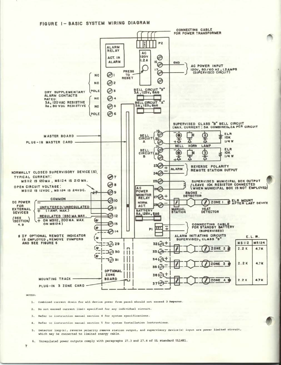
Wire Photoelectric Smoke Detector with Optional Horn Thermal Fire Lite 2400 4-Wire Photoelectric Smoke Dectector Fire-Lite 2412 2424. Basic system wiring diagram connecto cable for power ac power supervised class circuit max. Engineering Specification Battery Calculation.
Manual 51335 Engineering Specification. Per elr sell hmn. Â Regulated DC power output rated 100 mA.
HW-TG7LAF02 and HW-TG7LVF02 CLSS Communicator Manual. Section two An introduction to the suite of EN54 standards fire detection and alarm systems section two. Only withinthe range 112 to 126 inclusive.
069 -3D oqotf anotl 089-39 9 099-39 V Zl-9dN t 09 z XVü1 sdttre O. BRKT-9600 Mounting Bracket 51458. H365 A Series Addressable Thermal Detectors.
Operating instructions 2 pages Fire-Lite Keltron 95M3158 TTM-RPS Wiring Diagram Wiring diagram 1 pages Fire-Lite MS-2. 19 2 3 3 by circuit volt and ca to on. The last 2 are hot at all.
Fire-Lite Fire-Lite Miniscan MS-4024 Fire alarm control panel 39996. MS-9600 CE Addressable Fire Alarm Control Panel. This is a nearly exact model of the Fire-Lite Miniscan 424A fire_alarm fire_alarm_panel fire_panel panel We have converted your account to an Organization.
For an illustrated example please see Fig. Also fire and burglary alarm systems as well as CCTV survailance systems and Card access systems. MS-9600LS MS-9600LSC MS-9600LSE MS-9600UDLS MS-9600UDLSE.
4110amp supplies power to the battery saver relay on LGOG wire pin 11. AX-2 Auxiliary Module ZRM-1 Zone Relay Module ZRM-2 Zone Relay Module ZRM-4 Zone Relay Module RM-4 Relay Module RBZ-1 Ring by Zone Module RZA-4 Remote Zone Annunciator CZM-1 Cross.
Miniscan 112 1241
Miniscan 112 1241

Gkecd Ucv Jr3m
Miniscan 112 1241
Fire Lite Mcb 12 Master Control Board For Miniscan 112 1 Zone Facp
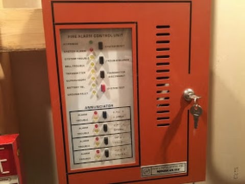
Mini Scan System Test 1 System Test 5 Fire Lite Miniscan 112 Youtube
Miniscan 112 1241
Miniscan 112 1241
Miniscan 112 1241
