The following lists Honeywells World Wide Web sites that will be of interest to our customers. Use the K terminal in place of the Y and G terminals on conventional or heat pump systems to provide control of the fan and the compressor through a single wirethe unused wire then becomes your common wire.
Honeywell Pro 3200 Wiring Diagram - If you're searching for video and picture information related to the keyword you have come to visit the ideal blog. Our website gives you suggestions for viewing the maximum quality video and picture content, search and find more informative video articles and images that fit your interests. comprises one of thousands of movie collections from several sources, especially Youtube, so we recommend this video for you to view. You can also bring about supporting this site by sharing videos and images that you like on this site on your social media accounts such as Facebook and Instagram or tell your closest friends share your experiences concerning the ease of access to downloads and the information you get on this site. This site is for them to visit this site.
Honeywell Motorised Valve Wiring Diagram For Gif 1024 950 Beauteous S8610u In 1024x931 1024x931 On Honeywell S86 Central Heating Heating Systems Wiring Diagram
Honeywell Security Communications Honeywell Security - Quality Assurance Dept Newhouse Industrial Estate Motherwell Lanarkshire ML1 5SB Scotland United Kingdom Tel.

Honeywell pro 3200 wiring diagram. I need help wiring a Honeywell Pro 3000 to a Goodman package unit GPH133OH21 Heatpump Terminal wires in the control box readsWiring Instructions - redR24v greenG9fanOrangeO Rev. Section 65 Main Power Current Sensor Wiring Diagram 19 Section 66 Line VoltageCurrent Sensor Diagnostics 20 Section 67 RS-485 Wiring 21 Section 68 RS-232 Communications 24 Section 69 Modem Wiring 26 Section 610 Modbus RTU Wiring 29 Section 611 BACnet MSTP Wiring 30 Section 612 Connecting E-Mon Class 3200 Meters to USB Key using RS485 30. The PRO-3200 Two-Reader Module provides support for up to two access control doors by providing connections for Wiegand or ClockData type readers supervised inputs and relay outputs.
Wiring Diagram for Connectors 1 through 7. If any damage to the shipment is noticed befo re unpacking a claim must be filed with the commercial carrier. Honeywell manual thermostat wiring diagram sample.
For N-485 Communication Connections twist the blue pair together and use as the. It shows the components of the circuit as simplified shapes and the power and signal connections together with the devices. 2 Separate the thermostat from the wallplate as per Figure 1.
Honeywell Organization WWW Address URL. For honeywell wall series 20 type thermostats connect the white wire. Use the orange pair as your data pair observing polarity.
T4 AND T1 PRO WIRING DIAGRAMS 3 33-0032501 1H1C. Issue A 32325422 WIRING DIAGRAMS Figure 1. This wiring must be separated from all other wiring by at least 25 and cannot be installed in the same conduit as any other power limited wiring.
You can either mount the board in a rack or open and flat. 3 Position the wallplate against the wall and mark hole positions with a pencil. Honeywell Pro Series thermostat Wiring Diagram wiring diagram is a simplified adequate pictorial representation of an electrical circuit.
Circuit honeywell thermostat wiring diagrams manuals are utilized for the design circuit structure construction such as pcb structure and upkeep of electrical and electronic machines. External drain shield to the appropriate earth ground on one end. S Indoor and Outdoor Wired Sensors.
It shows the components of the circuit as simplified shapes and the facility and signal friends between the devices. Note that the screw is captive and cannot be removed from the wallplate. Two 2 prox switches option Figure 2.
Two 2 electromechanical switches option Figure 3. Honeywell Pro Th4000 Wiring Diagram wiring diagram is a simplified usual pictorial representation of an electrical circuit. Heat Pump with Electric Aux Heat M36922 1H1C HEAT PUMP WITHOUT AUX HEAT.
Wiring Instructions for the MICRO SWITCH VPX Series. Four 4 electromechanical switches option. The thermostat uses 1 wire to control each of your HVAC systems primary functions such as heating cooling fan etc.
1 Loosen the locking screw at the bottom of the thermostat. The THP9045A1023 Wire Saver Module is used on heatcool systems when you only have four wires at the thermostat and you need a fifth wire for a common wire. Support 1-888-423-9883 QA Faxback TACFACS 1-800-525-7439 Service Asia Pacific Honeywell.
If you rack-mount the board only one edge is accessible for wiring. Its easy to use and compatible with the Windows Mac Q and Linux platforms. Click the icon or the document title to download the pdf.
440 1698 738200 Email. Heat Pump without Aux Heat 2H1C. See wiring diagrams in Section 2 - Installation.
The battery leads and primary AC main power wiring is non-power limited. All interconnecting wire must be ULULC Listed rated and suitable for the use. Organization Phone Number United States and Canada Honeywell 1-800-423-9883 Tech.
See the diagram below for what each wire controls on your system. Y Compressor Stage 1 Cooling Y2 Compressor Stage 2 Cooling G Fan. Wiring Diagram software software is a specially designed application in which the design of a wiring diagram with built-in symbols is automated.
ALM OUT PV F FUNCTION AUTO TUNE MAN-AUTO RESET SET UP RUN HOLD C R L 12 12 SP 2300 2300 DISPLAY M A Figure 1-1 UDC2300 Operator Interface. HONEYWELL V8043 ZONE VALVES 1 TH TR TRANSFORMER R 24 VOLTS END SWITCH. Contains all the essential Wiring Diagrams across our range of heating controls.
Diagram Case Tractor Wiring Diagram Full Version Hd Quality Wiring Diagram Avdiagrams Fanofellini It
Diagram Wiring Diagram Aegpetence Full Version Hd Quality Diagram Aegpetence Avdiagrams Fanofellini It
Diagram Estop Wiring Diagram Trip Full Version Hd Quality Diagram Trip Avdiagrams Fanofellini It
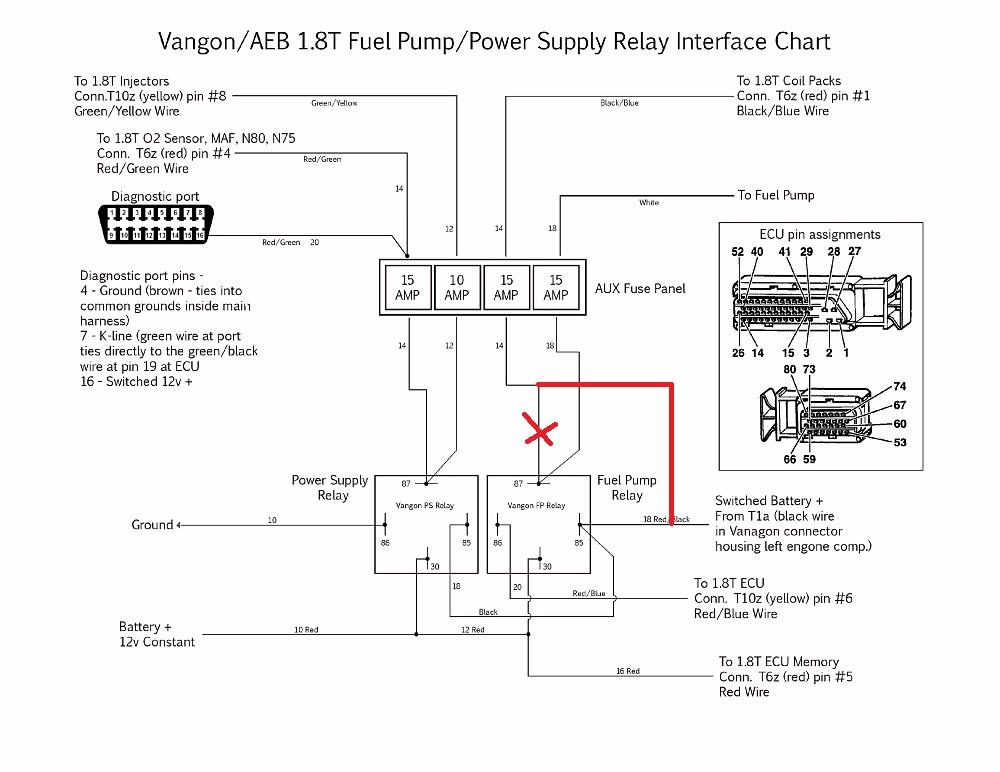
Diagram Passat 1 8t Wiring Diagram Full Version Hd Quality Wiring Diagram Diagrammit Fanofellini It
Diagram Basic Landline Diagram Full Version Hd Quality Landline Diagram Odiagrami Fanofellini It
Diagram 2008 Subaru Wiring Diagram Full Version Hd Quality Wiring Diagram Diagrammit Fanofellini It
Diagram 440 Dodge Wiring Diagram Full Version Hd Quality Wiring Diagram Odiagrami Fanofellini It
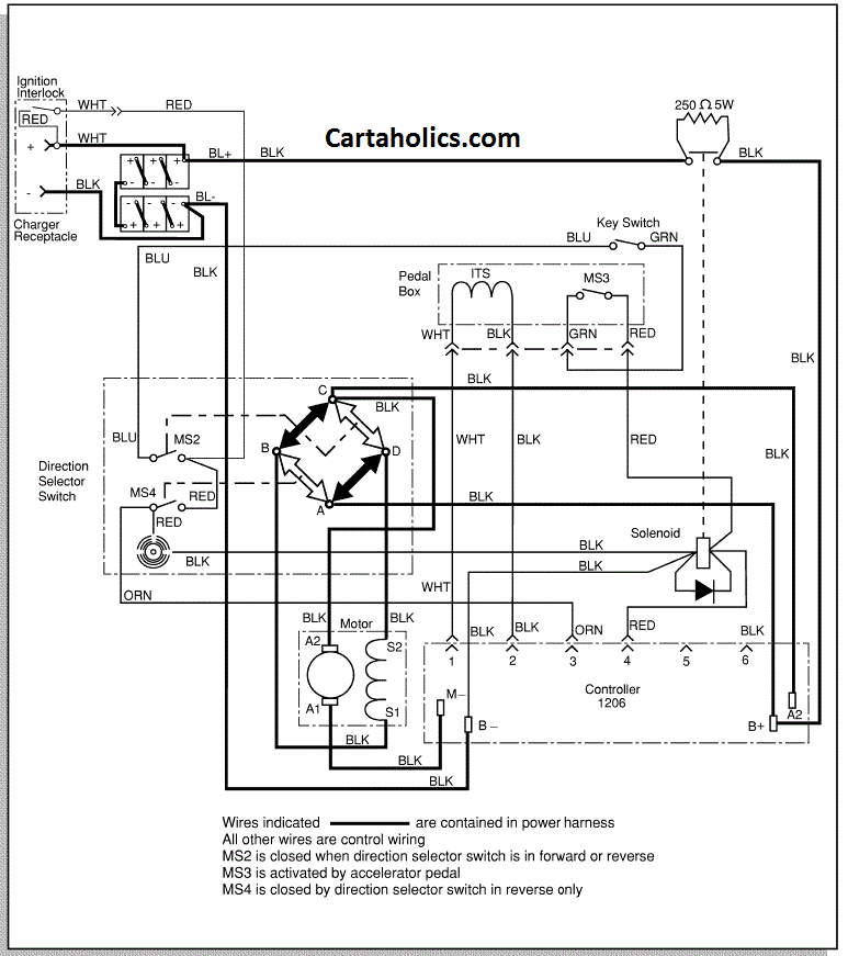
Diagram Ez Go Txt Wiring Diagram Full Version Hd Quality Wiring Diagram Odiagrami Fanofellini It
Diagram 95 Blazer Wiring Diagram Full Version Hd Quality Wiring Diagram Odiagrami Fanofellini It


