Dont connect anything to the NC tag. 4 After all the buttons are grounded wire a single strand from each button to an assigned iPac slot.
Ipac 4 Wiring Diagram - If you're looking for video and picture information related to the keyword you have come to visit the right site. Our website gives you suggestions for seeing the highest quality video and picture content, search and locate more informative video articles and images that match your interests. includes one of thousands of video collections from several sources, particularly Youtube, therefore we recommend this video that you view. This site is for them to stop by this site.

I Pac 4 Wiring Kit Retro Active Arcade
This is done by plugging the IPAC into your computer and the keyboard into the IPAC.

Ipac 4 wiring diagram. Black wire is the ground. What you do is wire switches to the device and then program each switch. Yellow is connected to iPac.
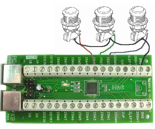
Below is a diagram showing an example of 3 joystick micro-switches connected to inputs on the I-PAC board. How to wire LED Standard Arcade Buttons and I-Pac 2 Switch Pt 2. No interaction or delays vital for multi-button games such as fighting games.
Pac C2r-chy4 Wiring Interface. Diagram Harley Flh Wiring Harness Full Version Hd Quality Soadiagram Ca Giancesare It. Step 4.
The worlds most advanced PC interface for buttons and joysticks. View in high resolution. 0 In the following steps use this wiring diagram for reference.
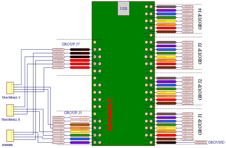
Each joystick has 5 wires one being the ground and the other 4 for each direction. After installing the joysticks we need to wire them onto our IPAC. A 110 I-PAC 4 Wiring kit will come with 48 wires total.
Yes you can connect the LEDs to 5V and ground but unless they are 5 volt LEDs they will need resistors in series. 1x black wire 8 in. Feb 22 2.
I assume that most of you are already familiar with the functionality of the IPAC2 but I will briefly describe what it is and how it is tied to the RetroPie. Reply 12 on. 1x green wire 4 ft.
When your button closes a circuit it triggers the iPac to signal your computer to enter a specific key. Since I could not find any wiring diagram online I checked each pin myself using my multimeter. You could instead wire Button 1 to 1SW4 L Shift reprogram the I-PAC so 1SW4 sends L Ctrl and off you go.
The kit will have 110 AND 187 wires. Each player will have 12 wires. 1x blue wire 4 ft.
2 To do this consult the diagram above and locate the correct pair of wires at the of the WinIPAC utility so check out the I-PAC pages for further informationDont connect anything to the NC tag. 2 Strip 12 of insulation off one end and 34 off the other. Any insulated stranded wire will do providing it is thick enough to be gripped by the screw connectors.
Allow about two to three inches extra to play with. The value of the resistor depends on the LED but as a general rule use 220 ohm. Multi-mode operation emulates either keyboardmouse with 56 available keycodes more than enough for 4 players or dual gamepadmouse or dual Xinput controllers.
Before you begin cut the following wires and strip the ends. 110 I-PAC 4 Wiring Kit. Buy PAC C2R-CHY4 Radio Replacement Interface for Chrysler.
You can use any colour you want these are. 1x black wire 8 in. Open the WinIPAC Interactive Panel Designer 3.
If playback doesnt begin shortly try restarting your device. 4x 187 Joystick Signal Wires per player 16 Total. In the pictures the START button is shown embedded in cardboard.
IPAC2 Button wiring When the cabinet was finally built it was time to wire the button switches to the IPAC2 Controller. The wires are separated into four different colors to differentiate between the four players. The gauge of wire used is not critical.
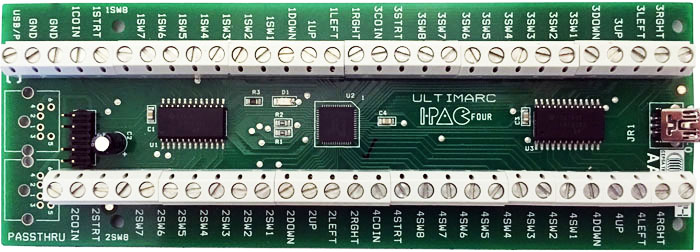
I-PAC is much more than a keyboard encoder. I-PAC 4 Keyboard Arcade Encoder. The kits are assembled with the following configuration in mind.
IPAC4 and LEDs - Question about power. 1x black wire 4 ft. 3 On 34 end twist the strands double over insert into disconnect and crimp it tight as in F - J.
I-PAC 4 in key mode breaks through the USB simultaneously-pressed-switch limit of 6 switches plus ctrlaltshift which afflicts all. I had a similar question and the answer was a device called the IPAC. The gauge of wire used is not critical.
Click Here For Wiring Diagram I-PAC 4 has 56 inputs each with its own dedicated microprocessor pin. September 05 2010 031158 pm. Automotive XSVINAV Wiring Interface -Allows you to connect a new car stereo in select.
This may be a bit complicated since we need to modify the 5-wire cable to work with our IPAC4. The wire we supply in our wiring kit is 16 X 02 mm. Multi-mode operation emulates either keyboardmouse with 56 available keycodes more than enough for 4 players or dual gamepadmouse or dual Xinput controllers.
View in high resolution. Then press the switch you want to program and the IPAC will tell you to press. Diagram enviro tech fan coil unit wiring full version hd quality ironedgediagram bagarellum it williams hhq diagramsys masteruninauto low static horizontal basic lh b aeroventic hh022w2b401r30 c 115v 4 rows cw or hw with electric heat 2 200 cfm 207 805 btu waterside ceiling void units eaton gas wall furnace jdiagram ebtx brochure pdf ifb no uhm116800417 amendment Read More.
4x orange wires 3 in. No interaction or delays vital for multi-button games such as fighting games. Ipac 4 wiring diagram.
Below is a diagram showing an example of 3 joystick micro-switches connected to inputs on the I-PAC board. Finally you could instead wire Button 1 to 1SW5 Z reprogram the I-PAC so 1SW5 sends R reprogram MAME so P1B1 was R in all games and off you go. Xin Mo Wiring Diagram.
PAC C2R-CHY4 Radio Replacement Interface for Select Chrysler Dodge and output wire and all the necessary output wires for a navigation radio install. 4x orange wires 3 in. Before you begin cut the following wires and strip the ends.
This device is a keyboard emulator. Note that I do not show theWiring Buttons with a JPAC or IPAC. 1 Cut correct length of red wire to get from the I-pac to the switch.

Some Easy To Understand I Pac J Pac Pac Drive Opti Pac Mini Pac Guides

I Pac 4 Usb Arcade Encoder Retro Active Arcade

Lifan 125 Wiring Diagram Wire Center Within Lifan 125 Wiring Diagram Autocad

Ipac 4 Wiring Diagram For Two Button Cab Arcade1up

Diagram Tv Stero Wiring Diagrams Full Version Hd Quality Wiring Diagrams Avdiagrams Fanofellini It
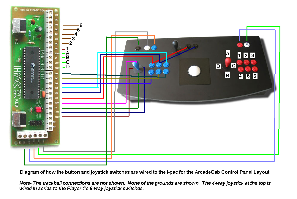
Arcadecab Mame Cabinet Plans 2 Wiring The Control Panel
Control Interfaces I Pacs I Pac4
Control Interfaces I Pacs I Pac4
Welcome To Ultimarc The Ultimate In Arcade Controls
