Use with building wiring junction box for quick connect to Power Base AI Jumpers under raised floor. Er14-50 1214 volt 50 amp replaces Generators on Small Block Continental Equipped Aircraft view our Model Eligibility for fit information Installation Instruction 07-01321.
Plane Power Er14 50 Wiring Diagram - If you're searching for video and picture information linked to the keyword you have come to visit the right site. Our website provides you with suggestions for seeing the maximum quality video and image content, search and locate more enlightening video articles and images that match your interests. includes one of thousands of video collections from several sources, particularly Youtube, therefore we recommend this video that you see. You can also bring about supporting this website by sharing videos and images that you enjoy on this site on your social networking accounts such as Facebook and Instagram or educate your closest friends share your experiences about the ease of access to downloads and the information you get on this website. This blog is for them to visit this website.
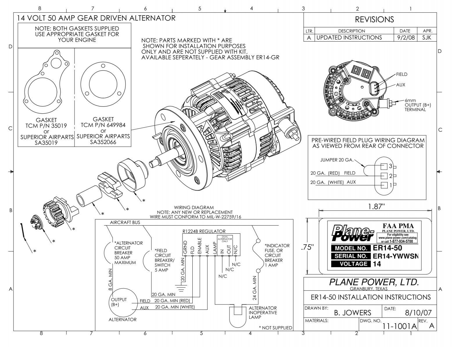
11 1001 Rev A Sheet1 Plane Power
50 - Instantaneous Overcurrent 51 - AC Time Overcurrent Relay 52 - AC Circuit Breaker 53 - Exciter or DC Generator Relay 54 - High-Speed DC Circuit Breaker 55 - Power Factor Relay 56 - Field Application Relay 59 - Overvoltage Relay 60 - Voltage or Current Balance Relay 62 - Time-Delay Stopping or Opening Relay 63 - Pressure Switch.
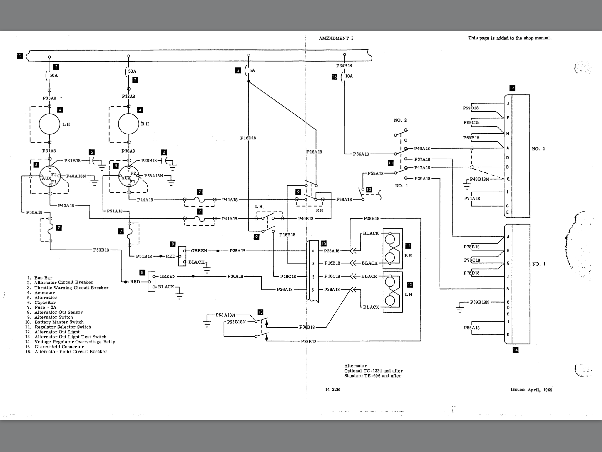
Plane power er14 50 wiring diagram. Aircraft Make Eligible Models STC Number Plane-Power Models. The circuit diagram of a. Wiring Diagram Pics Detail.
Ensure that internal jumper 1 and internal jumper 2 of the R1224B regulator are set for 14V operation See. Plane-Power also manufactures an alternator kit for experimental aircraft applications that comes complete with required brackets spacers internal cooling voltage regulation choice of internal or external and over-voltage protection. Plane-Power alternators are FAA PMA certified to replace the vast majority of popular general aviation alternators.
Aircraft Alternator Owners Manual LIST OF ILLUSTRATIONS PAGE Figure 21 - Alternator Simplified Electrical Diagram 2-1 Figure 22 - Stator Wiring Diagram Typical 2-2 Figure 23 - Typical Alternator Cutaway Basic Components 2-3 Figure 24a - ES-10024- Front View 2-5 Figure 24b - ES-10024- Rear View 2-5 Figure 25a - ALV-9610 Front View 2-6. Both belt and gear drive. To test the power module and coil a unplug the 3-way connector leading to the distributor and connect by means of a small piece of wire the blue wire to the black wire leading to the power module.
Top View Power Base AI Ceiling Distribution Wall or Column Side View. Alternate names of surge protectors are surge suppressors power strips transient suppressors. If the replaced generator had the smaller shaft 50 the ER14-50 installation may use the existing gear assembly.
Power surges can cause by defective wiring faulty devices and down power lines at the power source that can cause power surges too. Models 40 thru 70 amp. Pre-wired field plug wiring diagram as viewed from rear of connector 11-1001a a r1224b regulator a updated instructions only field aux 8 ga.
The ER14-GR can be used in place of the G-Pack if a new alternator to engine gear is needed at the same time. The primary power section is the backbone of the electrical system. Prestolite ALV series 100 amp.
The Plane-Power brand delivers aircraft alternators with outstanding performance value and installation flexibility. Surge Protector Circuit Diagram. Reside Beside Planes Benching or Intuity top feed to make quick connect to Power Base AI Jumper installed above dropped ceiling.
The electrical system on your aircraft can be thought of as having two major sections. 12 rows Plane-Power Models. S205 - 18R S205 - 20F S205 - 20R S208 S208A w.
Refer to Model Eligibility for your more information and additional models The Plane Power R1224 Voltage Regulator is a solid-state voltage regulator with over-voltage protection field short over current protection and reverse. CAUTION E-Series engines E-165 E-185 E-225 use a unique gear and CANNOT use the gear included in the ER14-50 assembly. Primary power and secondary power.
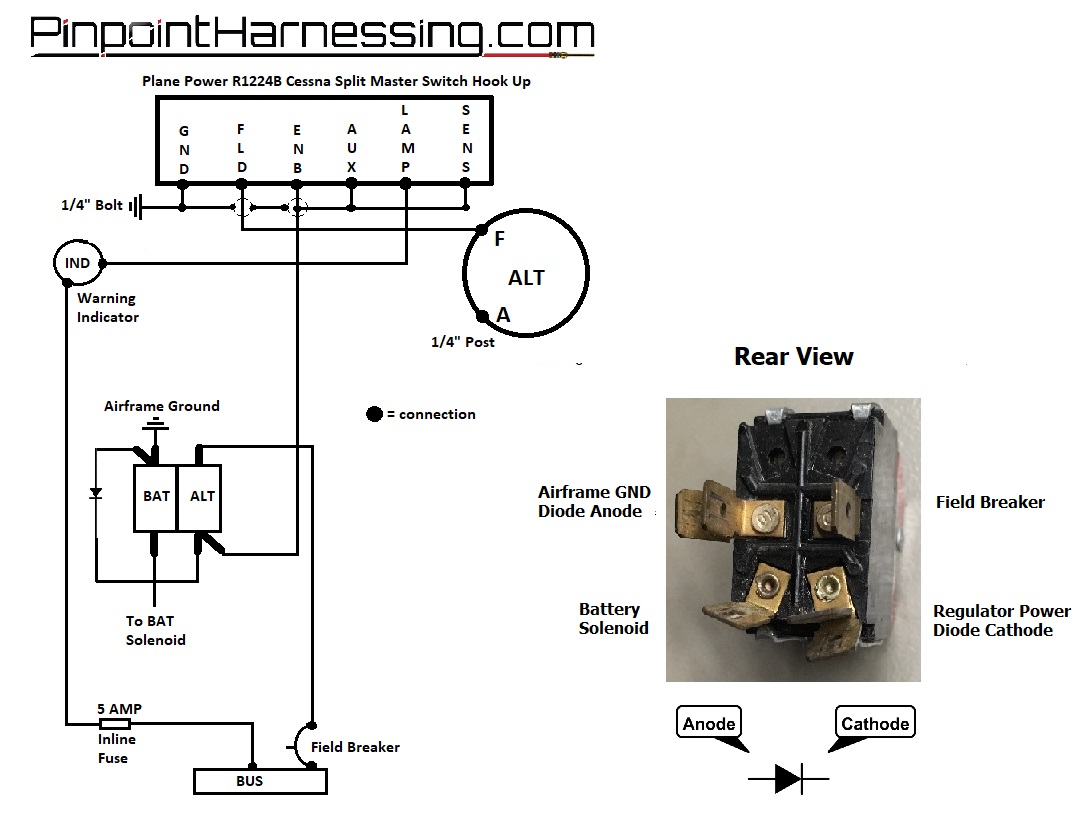
If no spark is produced the power module is suspect. It includes the larger wires in the electrical system that tie together the battery starter alternator and main power buses. Plane power alternator wiring diagram Plane Power Alternator Wiring Diagram Wiring Diagram for Alternator Chevy Valid Aircraft Alternator Wiring Diagram.
If no lash is detected remove ER14-50 and correct the cause before proceeding. PMA certified solid-state aircraft voltage regulators with over-voltage protection field short protection reverse battery protection precision load sharing and support for either 14-volt or 28-volt applications with the simple change of two jumpers. 14V 28V replaces Ford Electrodelta Prestolite Interav Wico FVR and more voltage regulators.
Ford 14 28 volt 60 amp belt. Min 9208 dual alternator sjk faa pma plane power ltd. F260 F260B F260C F260D F260E F260F w.
4688 119 mm 15 381 mm. Discover information regarding Plane-Power aircraft alternator troubleshooting service warranty maintenance applications and videos here. As this connection is made a spark is produced at the HT lead.
TCM 28 volt 60 amp. Products FAA PMA Certified Alternators. Check drive gear lash by carefully moving the ER14-50 cooling fan on rotor back and forth Typical lash 075 on outer diameter of fan blade.
TCM 28 volt 100 amp.
Regulators
Https Planepower Aero Wp Content Uploads 2018 02 Stc Sa10921sc Afms 003 11 0000 Pp Pdf
Plane Power Ltd Conversion Kit Er14 50 Alternator
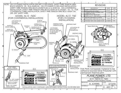
Installation Instructions Plane Power
Https Planepower Aero Wp Content Uploads 2020 05 Er14 50 Installation Instructions 1 Pdf
Https Planepower Aero Wp Content Uploads 2018 02 Stc Sa10921sc Afms 003 11 0000 Pp Pdf
Plane Power Ltd
Regulators
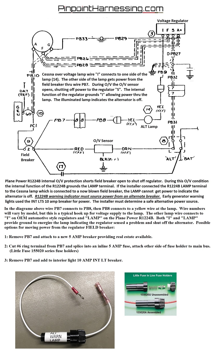
Csobeech Inside Bonanza Baron Voltage Regulators
