This manual is for reference only and was created to serve as an addition to the FISHER Service Training Manual. 46149 57686 You Save 11537.
Fisher Fish Stick Wiring Diagram - If you're looking for video and picture information related to the keyword you've come to pay a visit to the right site. Our website provides you with suggestions for viewing the maximum quality video and picture content, search and find more enlightening video content and graphics that match your interests. comprises one of tens of thousands of video collections from various sources, particularly Youtube, therefore we recommend this movie that you see. You can also contribute to supporting this website by sharing videos and images that you like on this blog on your social media accounts like Facebook and Instagram or tell your closest friends share your experiences concerning the ease of access to downloads and the information that you get on this website. This site is for them to stop by this website.
Fisher Plow 3 Wire W 4 Port Module
This may also be good for adapting a Fisher joystick to another pump set up.
Fisher fish stick wiring diagram. Reassemble the fuse holder and cap using a SFE-6 fuse PN 80168. Rating Select Rating 1 star worst 2 stars 3 stars average 4 stars 5 stars best Name. Snow plow parts diagrams.
We use few parts so easy and cheap. I did this in excel but had to convert it to word to be a valid file here. Add To Pick List.
This is a new OEM Fisher Fish-Stik Control Kit 9400. Joined Dec 28 2018. This will also help in quickly diagnosing wiring issues as well.
This can be used with a Straight Plow Blade. Click on the number that corresponds to the part you need. It uses a 12V battery to convert to 220V AC or 110VAC.
This material is not complete may not. We carry great options such as the Fisher Xtreme V handheld controller or the Fisher Straight Blade joystick controller both of which have FREE shipping. I put led turn signals in the plow lights to l.
A circuit is usually composed by many components. FISHER SNOWPLOW CONTROLS. The first element is symbol that indicate electrical component from the circuit.
CLICK ON CIRCLE WITH NUMBER FOR PART NUMBER PRICING VERIFY 4 PIN SQUARE OR 10 PIN ROUND CONNECTOR. Add To Pick List. It helps in catching fish easier.
Wiring a snow plow with 9 wires 1 harness and 2 relays. The other thing that you will discover a circuit diagram could be traces. SNOW PLOW PARTS DIAGRAMS.
How to repair the buttons in the Fisher EZ-V 9-button hand-held plow controller. Install a label PN 56423 onto the red wire nearest to the fuse holder. Fisher Plow Wiring Diagram Minute Mount 2.
Headlamp electrical schematics fisher plows 2 right side plow lamp p t sig headlamp assist in diagnosis and repair of fisher fi minute mount fi snowplow electrical systems diagrams and wiring diagram for minute mount 2 fisher plow readingrat original minute mount wiring relay style at wiring diagram wiring. Motor Relay Kit FLEET FLEX. The Control Kit includes the Control Body Keypad PCB Assembly with Keypad Label Harness Straight Blade 6-Pin Tapping Screws and Parts Bag with the Control.
Remove the red wire and spring from the white fuse holder body. 14-20 x 14 Hex Washer-Head Thread-Rolling Screw. This is the simple electric fish shocker circuit or fish stunner.
The module sees a ground when you plug in the grill plugs then it turns on the controller. Here is a picture gallery about fisher snow plow wiring diagram complete with the description of the image please find the image you need. No tapping into headlights no connectorsOne change.
Yes the module controls power to the controller. Fisher Minute Mount Plow Controls. FISHER EZ-V FISH-STIK CONTROL KIT 10-PIN ROUND 9800.
6 Dec 3 2019. There are two things that will be found in any Fisher Plow Wiring Diagram. Add To Pick List.
OEM part number 96449 96450Repair kit available at. Whatever your snowplow weve got the controller for you. Fisher snow plow parts diagrams.
EZ-V FISH-STIK CONTROL KIT. This circuit converts voltage from 12V battery to AC. Item 1 fisher snow plow minute mount wire harness kit - for fish stick controllers 1 - fisher snow plow minute mount wire harness kit - for fish stick controllers 21999 Free shipping.
Fisher Snow Plow Wiring Diagram Golkit inside Fisher Snow Plow Wiring Diagram image size 1024 X 690 px and to view image details please click the image. 10 rows Harness Straight Blade 6-Pin White Connector. We have collected several photos ideally this photo serves for you as well as help you in finding the response you are trying to find.
Reconnect the red fuse holder wire to the power source. Fisher minute mount 2 wiring diagram - thanks for visiting my website this blog post will certainly review concerning fisher minute mount 2 wiring diagram. If youre looking to get a new or replacement Fisher plow controller browse our selection below for handheld and joystick controllers.
Components of Fisher Plow Wiring Diagram and Some Tips. Insert the red wire and the short spring PN 56469 into the fuse holder body. This had a 6-Pin Square Connector and cannot be interchanged with other controls.
9400 FISHER SNOW PLOWS GENUINE REPLACEMENT PART - CONTROL FISH-STIK STRAIGHT BLADE 6 PIN. I would get the wiring diagrams and start looking for missing voltage. Click on the links below to view parts diagrams.
It contains information on noncurrent products that are often the subject of technical questions and problems. XLS XTREME V EZ-V FISHSTIK - XLS XTREME V.

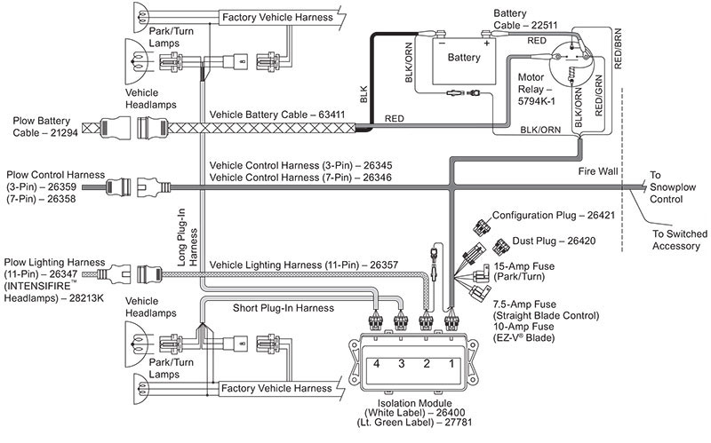
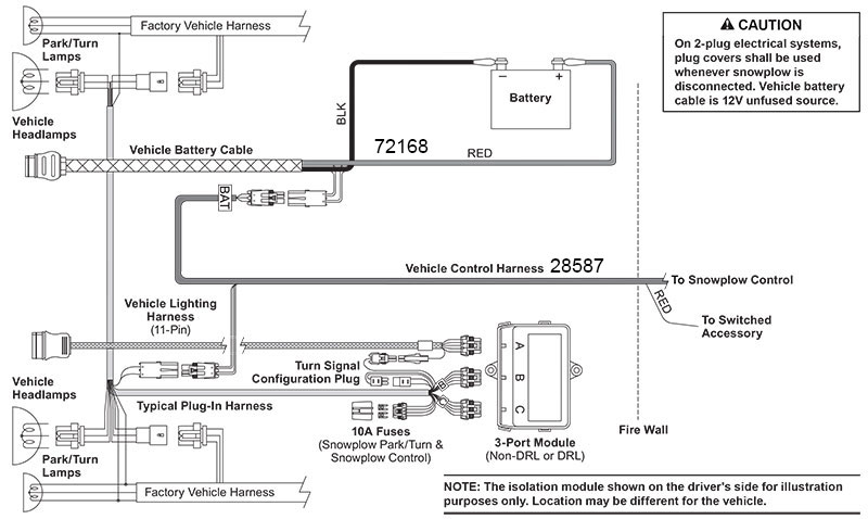
Homesteader Vehicle Side Harness Snow Plow Parts List Fisher

Pin On All Show

15 Basic Engine Wiring Diagram Engine Diagram Wiringg Net Volvo Wiring Diagram Alternator

Diagram Wiring Diagram For True Zer Full Version Hd Quality True Zer Avdiagrams Fanofellini It
Diagram Wiring Diagram Ats Genset Full Version Hd Quality Ats Genset Odiagrami Fanofellini It
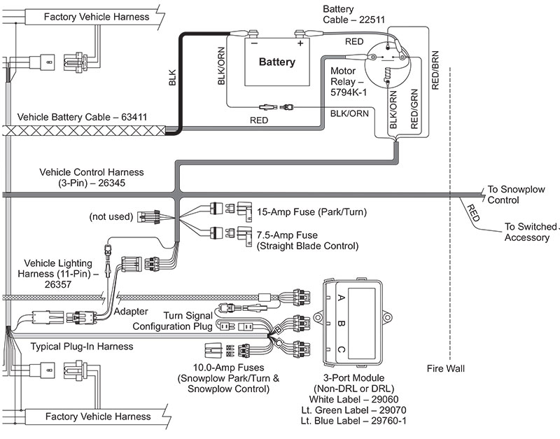
Fisher Snow Truck Side Wiring Kits Zequip Truck Parts Store
Diagram Ceiling Fans Wire Diagram Full Version Hd Quality Wire Diagram Avdiagrams Fanofellini It
Fisher Snow Truck Side Wiring Kits Zequip Truck Parts Store

Honda Xrm 125 Engine Diagram In 2021 Wiring Diagram Electrical Wiring Diagram Engine Diagram
