Item 4 Interlink 5709L Heatcraft USA Defrost Termination Switch 3 Wire 3 - Interlink 5709L Heatcraft USA Defrost Termination Switch 3 Wire. A wiring diagram is a simplified traditional pictorial representation of an electric circuit.
Heatcraft 5709l Wiring Diagram - If you're searching for picture and video information linked to the keyword you have come to visit the ideal site. Our website gives you hints for seeing the maximum quality video and picture content, hunt and locate more enlightening video content and images that match your interests. includes one of tens of thousands of movie collections from several sources, especially Youtube, therefore we recommend this video that you view. This site is for them to stop by this site.

Page 11 Of Heatcraft Refrigeration Products Humidifier 25005601 User Guide Manualsonline Com
For professional use only.

Heatcraft 5709l wiring diagram. Heatcraft - 5709L - 3 Wire Fan Defrost Terminal 55 F-35 F. Product must be used in accordance with such labeling and documentation. Use genuine OEM parts for safety reliability and performance.
The common elements in a very wiring diagram are ground energy wire and connection output devices switches resistors logic gate lights etc. Heatcraft Refrigeration Products provides climate-control solutions for commercial refrigeration and industrial applications in North America and beyond. If its wired in series with the heaters from 3 to N its correct.
Refer to all information warnings and instructions on product and package labeling and accompanying documentation provided by the product manufacturer. The defrost terminationfan delay control is a temperature activated single-pole double-throw spdt switch controlled with a remote sensing bulb. Wiring Diagram Pics Detail.
2 - blue label F close on temperature rise SPST L open on temperature rise SPST 2. 0 users rated this 5 out of 5 stars. How to Read Wiring Diagram.
25 Heatcraft 5709L Wiring Diagram Pics. 22 Hampton Bay Ceiling Fan Light Kit Wiring Diagram Pictures. 5709L 3 WIRE DEFROST TERM SWITCH.
5709l defrost termination switch 25309801s motor 115 208-230 5060 1ph 1650 psc sp 25309101s motor 115hp 208-230 1550 516 ccwsepsc 25309501s motor 115 120115 50601 1600 psc teao 5708l thermostat heater limit 18leads o75 c40 5140c blade 12 in 23 deg 312 bore cw std 25317701s motor-fan bldc 208-230v lop service. 3 is opposite of no. Description 3 Wire Fan.
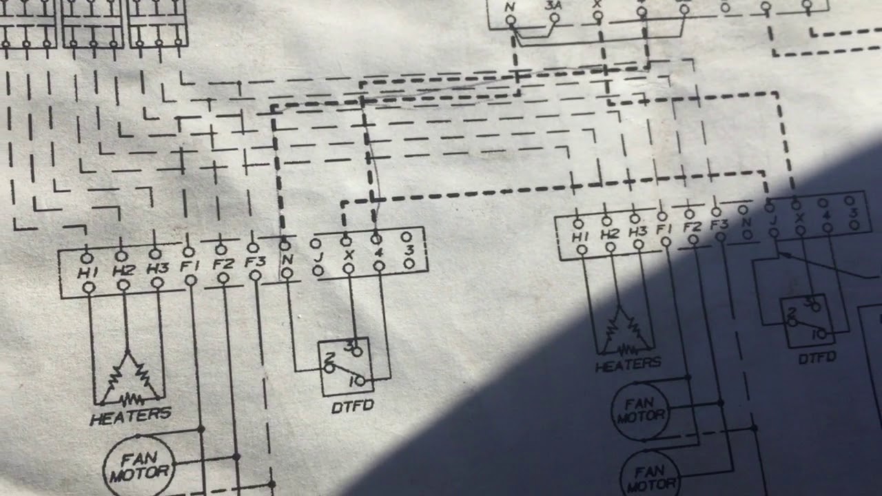
They replaced those two with a single three-wire. Item 2 Interlink 5709L Heatcraft USA Defrost Termination Switch 3 Wire 2 -Interlink 5709L Heatcraft USA Defrost Termination Switch 3 Wire. 2 either opens or closes temp.
Heatcraft - 5709L - 3 Wire Fan Defrost Terminal 55 F-35 F. 30 Heat Pump Diagram Pics. For more than 50 years Bohn has been a leader in products built for the supermarket grocery store restaurant and retail industries.
It shows the elements of the circuit as simplified shapes as well as the power and signal links in between the gadgets. One close-on-fall klixon for the evap fans and one close-on-rise klixon for the defrost termination. To read a wiring diagram first you have to know what fundamental elements are included inside a wiring diagram and which pictorial symbols are employed to represent them.
The proper diagram should be 2 on p40 for a single evaporator with electric defrost. May 4 2020 by. 31 Siemens Plc Wiring Diagram Pdf Background.
19 Forklift Parts Diagram Images. For extra long runs 16 gauge wire may be required. 30 out of 5 stars based on 1 product rating.
Download 2007 Dodge Charger Rt Radio Wiring Diagram Images. Defrost termination fan delay switch wiring diagram Diagram Defrost Termination Switch Wiring Diagram Klixon 5709L Wiring Diagram 5709l Wiring Diagram. Item 5 Interlink 2890109 Low Temp Defrost Termination and Fan Delay Thermostat.
Whereas the original fan switch closed power to the fan motors. Bohn Genuine OEM replacement part. Assortment of heatcraft walk in freezer wiring diagram.
It originally had a four-wire setup. The problem was that the original defrost switch closed common to the X terminal. 33017 20425L153-B22-B54 Heatcraft 5708L L 75 40 18 w quick connects 33025 20425D56-520-B10 Heatcraft 5709L D 55 35 18 w quick connects 1DSPDT no.
5709l 1 defrost thermostat 89840240 1 air deflector 91179001 1 motor mount bblm15 25300701s 2 motor - shaded pole 115160 21901002 1 tstat switch 24700601 1 coil heater 24700603 1 drain pan heater 29301101 1 txv valve 29301201 1 solenoid 40401001 1 drain pan drain fitting included 4751c 1 defrost thermostat 5054d 2 fan guard 5109e 2 fan blade. Our linde forklift manual inventory includes service parts and maintenance information in pdf format. We manufacture unit coolers condensing units condensers compressorized racks refrigeration systems and refrigeration controls through five market-leading brands including Bohn Larkin.
Forklifts parts equipment has been a leader in the lift truck industry since 1989 providing forklifts service and parts for all makes. Be safe not fast. The control shown also happens to be an adjustable type.
Body parts dont grow back. Figure 1 shows an installation of an adjustable defrost terminationfan delay control on. That two wire tstat is the heater limit HL.
Rise - red label no. Slave units if used - Connect the multi-out terminal on the master unit to the multi-in terminal on slave unit and the 24V 18 to 30 VAC from the master unit to the slave unit. Loading price EA Skip to.
5709L 3 WIRE DEFROST TERM SWITCH. Been seeing the mounting plate come off of some lately too. Interlink parts recommended stocking list 2020 25309501s motor 115 120115 50601 1600 psc teao 25309701s mtr 460v 5060hz 1 ph 115hp 33d te 25309801s motor 115 208-230 5060 1ph 1650 psc sp 25310001s motor-fan 13hp 208-230v 22a 1625rpm cc 2531191s motor 12h 230v 1075rpm 12dia cwse 2531193s motor 13h 230460v 1140rpm 12 cwccw 25314601s motor 460v 5060hz 13hp 1ph.
19 Forklift Parts Diagram Images. 1 is common white - no label no. Low voltage wiring must be run separate from other high voltage power wiring.
Fa 0016 Defrost Termination Switch Wiring Diagram Download Diagram
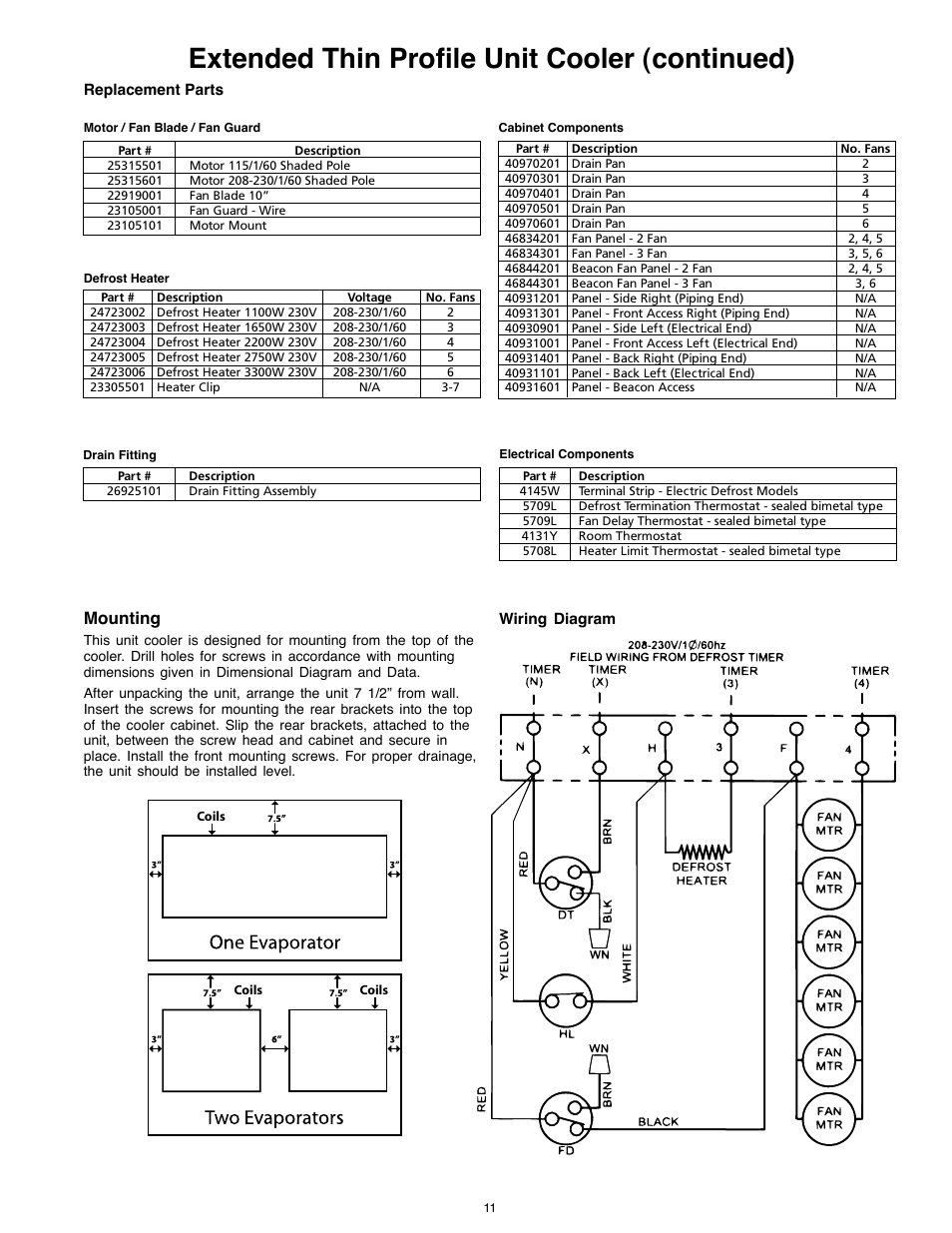
Extended Thin Profile Unit Cooler Continued Mounting Heatcraft Refrigeration Products 25005601 User Manual Page 11 20

Fa 0016 Defrost Termination Switch Wiring Diagram Download Diagram

Using Defrost Termination And Fan Delay Controls

Diagram 3 Wire Defrost Termination Switch Diagram Full Version Hd Quality Switch Diagram Diagraman Mbreporter It
Correcting Control Wiring For Defrost Termination Fan Delay Switches Youtube
