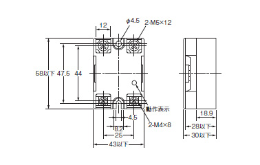
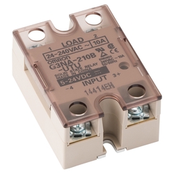
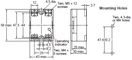
The orientation indicated by the external dimensions is not the correct mounting orientation. When ordering specify the rated input voltage.
Omron G3na 210b Wiring Diagram - If you're looking for video and picture information related to the key word you've come to pay a visit to the right site. Our website provides you with hints for viewing the highest quality video and picture content, search and find more enlightening video content and images that match your interests. comprises one of thousands of movie collections from various sources, particularly Youtube, so we recommend this video for you to see. This blog is for them to visit this site.
Solid State Relay G3na Omron Misumi Indonesia
R 10 k ohms 2W for the standard PLC application.
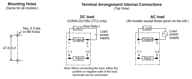
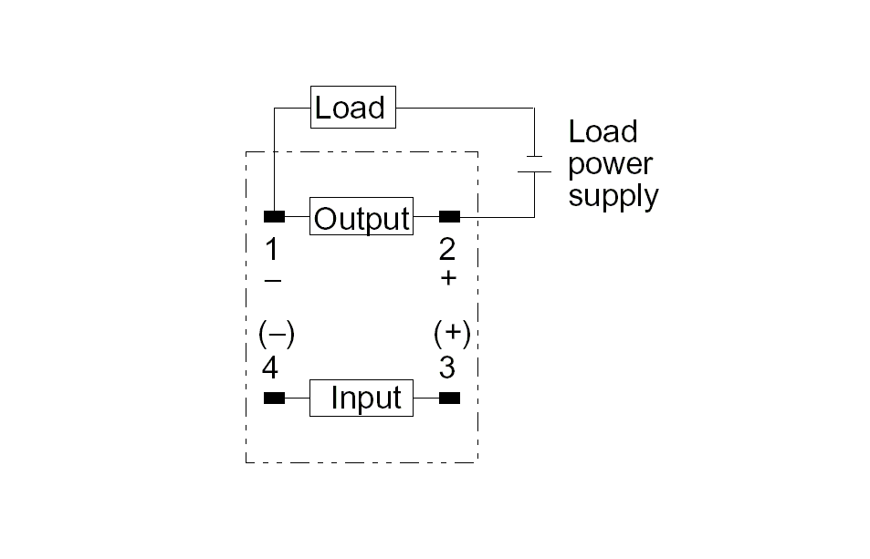
Omron g3na 210b wiring diagram. Built-in varistor effectively absorbs external surges. The screw terminals are labeled LOAD 1 and 2. G3NA-210B 01 to 10 A at 40C 01 to 4 A at 40C 150 A 60 Hz 1 cycle.
Model Rated voltage Operating voltage Impedance See note 1 Input current Voltage level. Contactor schneider catalog omron contactor 50shb100 Text. The following diagram shows concentric lines of magnetic flux when the permanent magnet is placed near the working gap.
Manuals and free instruction guides. Kubota Z122r Drive Belt Diagram Omron G3na 210b Wiring Diagram Diamond Contractor Logo Vector Road Dark Cloudy Sky Background Outline Medal Template Printable. OMRON Industrial Automation functions as a partner to help innovate worldwide manufacturing.
Page 8 Y92B-N50 Heat Sink for the G3NA-205B-UTU G3NA-210B-UTU G3NA-410B-UTU G3NA-D210B-UTU For surface mounting a 30 derating of the load current is required from the Load Current vs. 50 A at 200 to 480 VAC. Model Rated voltage Operating voltage Impedance See note 1 Voltage level Must operate voltage Must release voltage.
Find the user manual. 30 A at 200 to 480 VAC. Load Short-circuiting Do not short-circuit the load otherwise the Sensor may be dam-aged.
When an OMRON Heat Sink refer to Options or a heat sink of the specified size is used. Omron G3na 210b Wiring Diagram Vector Humidity Icon Road Dark Cloudy Sky Background Outline Medal Template Printable Printable Narrative Therapy Tree Of Life Template Printable Fluxx Cards Apprenticeships Logo Vector Archive. Omron Relay Electromechanical catalog X301-E-1.
When S1 is actuated the DC supply will energize the input of the SSR and the output will turn on illuminating the light bulb. Omron G3NA-210B-DC5-24 Solid State Relay Zero Cross Function Yellow Indicator Phototriac Coupler Isolation 10 A Rated Load Current 24 to 240 VAC Rated Load Voltage 5 to 24 VDC Input Voltage 44 out of 5 stars 8. Omrons G3PA G3PB G3NA Input current.
Do not store excess wire length in the CentriFlow Meter enclosure. The basic wiring diagram for testing a DC input solid state relay. G3NA-D210B G3NA-410B G3NA-420B G3NA-440B Faston omron g3na-205b relay wiring example R87F-PCJT omron g3na-220b-dc5-24 circuit diagram 50SHA30 50SHA40 omron fan speed control relay unit 60PFF30 HINODE 50SHA80.
Through our experience in sensing and control technology we enable manufacturers to operate with greater productivity and streamlined efficiency. Since the input current is 7 mA or less up to four units 7 mA 4 28 mA 30 mA maximum allowable current can be connected in parallel. The Omron G3NA Solid State Relay SSR.
This manual is also suitable for. When used with the proper OMRON heat sink thermostat terminals. When an OMRON Heat Sink refer to Options Order Separately or a heat sink of the specified size is used.
The following diagram shows a protective circuit example. Except G3NA-D210B-UTU Operation indicator enables monitoring operation. 20 A at 200 to 480 VAC.
G3na-205b-utu dc5-24 G3na-205b-utu ac200-240 G3na-210b-utu dc5-24 G3na-210b-utu ac100-120 G3na-210b-utu ac200-240 G3na-220b-utu. Protective cover for. 30 A at 200 to 400 VAC.
Contactor schneider catalog omron contactor 50shb100. 480 VAC G3NA-290B-UTU 24 to 240 VAC G3NA-490B-UTU 200 to 480 VAC When the appropriate size OMRON 480 VAC 24 FLA 144 LRA 480 VAC 10 A 200 VDC Note. 2021 128 May 29 Digital Tv Antenna Wiring Diagram.
When the AC mains is applied to the output of the SSR the light bulb should not illuminate. G3NA-210B-UTU 01 to 10 A at 40C 01 to 4 A at 40C 150 A 60 Hz 1 cycle. Connect load following the wiring diagram in Figure 2.
When long wiring is. Omron Electronic Components Company offers broad range of products that provide advanced device and module solutions centered on relays switches connectors and sensors to suit a variety of applications in the sectors of factory automation mobility energy management healthcare and officehome appliances. Opening S1 will again turn off.
Wiring Power Supply Voltage Make sure that the power supply to the Sensor is within the rated voltage range and do not apply 100 VAC or more if the Sensor is a DC model or otherwise the Sensor may explode or burn. Manufacture will be discontinued at the end of March 2017.
Theatrical Cue Lights Part 4 Stompville
Solid State Relay G3na Omron Misumi Indonesia
Omron Solid State Relay Wiring Diagram
Theatrical Cue Lights Part 4 Stompville
Omron G3na Series
G3na Solid State Relays Dimensions Omron Industrial Automation Australia
G3na 210b Ac100 120 Omron Solid State Relays Distributors Price Comparison And Datasheets Octopart Component Search
Omron G3na D210b Solid State Relay
Omron Solid State Relay Wiring Diagram
