It demonstrates how the electric cables are interconnected and can likewise reveal where components and also elements might be attached to the system. The GMDLBP will detect all door triggers through the data line for TYPE 2 and TYPE 3 vehicles only.
Gmdlbp Wiring Diagram - If you're searching for picture and video information related to the key word you have come to visit the right site. Our website provides you with hints for viewing the maximum quality video and image content, search and locate more informative video content and images that fit your interests. comprises one of thousands of movie collections from several sources, particularly Youtube, so we recommend this movie for you to see. This blog is for them to visit this site.

Diagram 1973 Vw Bus Ignition Switch Wiring Diagram Full Version Hd Quality Wiring Diagram Avdiagrams Fanofellini It
Next to the wire.
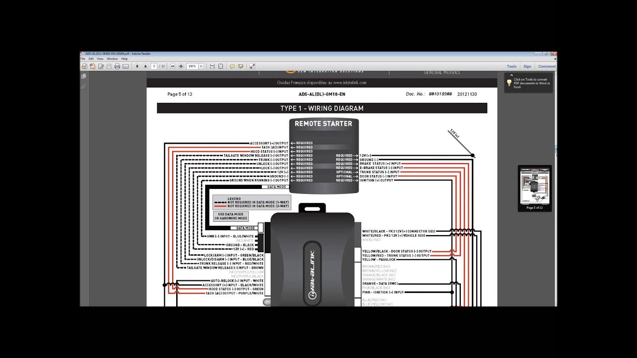
Gmdlbp wiring diagram. GM Doorlock Alarm and TransponderPasslock Interface. Blue 3 -pin Door Lock harness To GMDLBP Blue Green 3 -pin Door Lock harness To GMDLBP Green NOTE 1 The remote start has two parking light wires. It shows how the electrical wires are adjoined and can likewise show where fixtures and also elements may be linked to the system.
Relays are not required except in cases in which the outputs ground signal is insufficient. Guest Battery Charger Wiring Diagram. 1-way and 2-way compatible Range Xtender for any applicable XPRESSKIT solution.
Gm Ignition Switch Wiring Diagram. Remove the bluewhite wire from ground and connect to - ground when running status output from remote starter. Edwards 270 Pullstation Wiring Diagram Pdf.
70 Vw Wire Harnesses. XpressKit GMDLBP - Front included pin harness provides wires to connect to your factory system. Lace the loop antenna ring ar Note Move antenna loop as close to the front of the ignition cylinder.
-Compatible with manufacturers anti-theft content theft security systems-Maintains integrity of manufacturers anti-theft immobilizer system-No Key Required for operation NKR. Com has been informing visitors about topics such as GM Security System Bypass GM Passlock Bypass and Bypass. The document has moved here The GM Passlock System is a key-based fuel shutdown anti-theft system Passlock I Wiring Diagram This wire is located in the vehicles three-wire Passlock.
Bought the omega gmdlbp bybass module with it. P Rails In Les Paul Wiring Seymour Duncan User Group Forums. Dball2 Wiring Diagram.
Diagram Viper 5901 Wiring Full Version Hd Quality Rackdiagram Lavocedelmare It I Ve Purchased A Viper 5704 Remote Start And Alarm With Omega Ol Mdb All Bypass Module Was Wanting To See If Any One Has Diagram Viper Remote Start Relay Full. Compatible with manufacturers security and convenience functions. Wiring Diagram Tech Notes.
Golf Cart Battery Wiring Diagram. Transistor - doorlock outputs TECH NOTES. It is a standard widely used around the world.
The green wire connects to the Lock - Output GREEN wire in the 3 PIN DOOR LOCK PORT of the Excalibur The blue wire connects to the Unlock - Output BLUE wire in the 3. The violet wire connects to the wire going in to the back of Pin 2 on the vehicles diagnostic connector. Compact deisng with easy programming.
Delco Generator Wiring Diagram Delco Cs130 Alternators Hemmings Daily Credit. High security single-wire data transfer. Sometimes even in case you shut away from power some cabling might be connected in order to another.
Viper Clifford Python LE SST compatible. You will only use one of them. Six Tips for power wiring 1.
Goodman Fan Control Board Wiring Diagram. A P ound the vehicles ignition cylinder as shown. Check test wire connections and devices for power inside typically the box you usually are working in to stop electric shock just before working on all of them.
Maintains integrity of manufacturers anti-theft system. B Plug the 2 pin loop antenna ring connector into the 2 pin connector of the module. Accordance with the instruction manual may cause harmful interference to.
Maintains factory XpressKit GMDLBP Owners manual. EdwardsEST SPO manual pull station commonly used in Canada USA. As I post my wiring diagram I dont know if thats help to determine where they going.
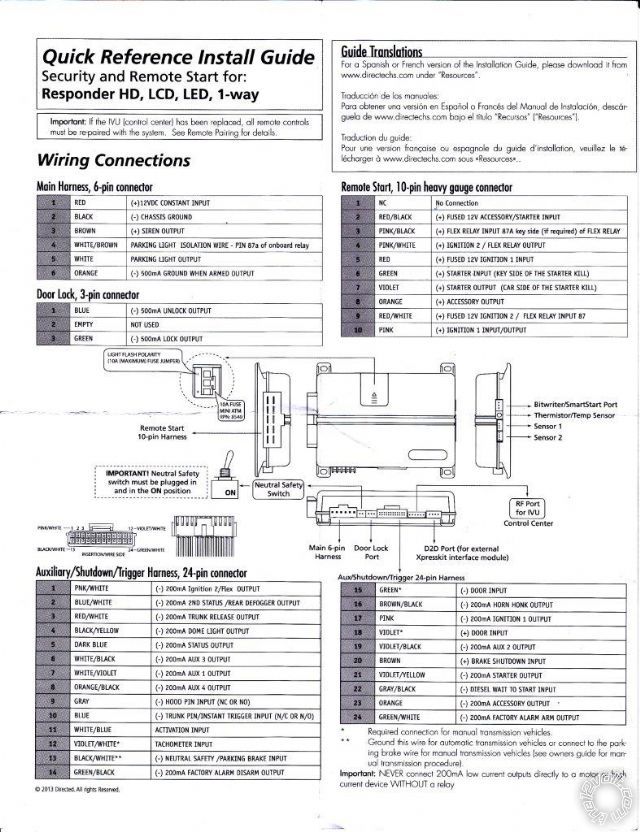
Guitar Wiring Diagram 1 Humbucker 1 Volume. Hooking everything up we get to the door triggers and the wiring diagram says grayblack at. In 6 pins pinkwhite the default setting is IGN2View attachment 28813 In 12 PINS WHITE-500mA10Amps GOING TO PARKING LIGHTS REDBLACK PARKING LIGHT INPUT SELECT 12VGROUNDView attachment 28810 BROWNWHITE GOING TO FACTORY CAR HORNView.
Aqua Rite Wiring Diagram Electrical System. Seymour duncan p rails wiring the telecaster guitar forum rail question 4 toggle les paul in a hh strat help esquire shpr 1s set triple shot or push pull pot 2 piece diagram first build grounding issues checking my mounts another hsh super installing shots on cheap makeover tonefiend com mine v2 postimages nucleus vw alternator full. Hampton Bay Ceiling Fan Wiring Diagram.
Wiring Diagram Tech Notes. An electrical wiring diagram is a basic graph of the physical links and physical format of an electrical system or circuit. Graphic Equalizer Schematic Diagram.
A fire alarm system has a number of devices working together to detect and warn people in any country of the EU. The GMBP is a 3 in 1 bypass solution which is compatible with the 1st generation GM Passkey used on the 99 Transport Venture Silhouette and the more common 2nd gen. Ensure you have the latest features and functions by updating firmware.
For reliable conversion of analog to digital all - input wires require a solid ground to activate each command function. Gy6 150 Wiring Diagram. READ Gmdlbp Wiring Diagram Database.
Yellow r-code wire black passlock ground wire ignition 2 output. Hagstrom Guitar Wiring Diagram. Gmdlbp Wiring Diagram PKALL is internet upgradeable and includes unlimited free firmware updates.
Passkey 3 as well as the Passlock II resistor code immobilizer. A circuitry diagram is an easy graph of the physical connections as well as physical format of an electric system or circuit. H2S5D1 STEP 1 98-05 GM Doorlock Alarm Immobilizer Integration Module.
GMDLBP GM Doorlock Alarm TransponderPasslock Interface Product Features-Wire to Wire compatible with any type of remote car starter W2W. On your vehicle wiring chart look up the wire for the parking lights.
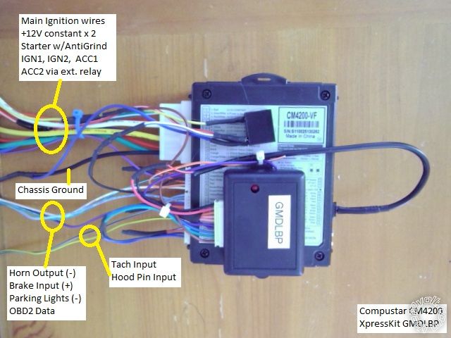
2003 2006 Gmc Yukon Remote Start Pictorial
2005 Silverado Viper 5706v

Cat 3126 Ecm Wiring Diagrams Caterpillar Ecm Catecm Wiring Diagram Diagram Wire

Gmdlbp Dalhems Manualzz
Http Www Mypushcart Com Help Txxxx Rs350 Gmdlbp Pdf

Diagram N14 Ecm Wiring Diagram Full Version Hd Quality Wiring Diagram Odiagrami Fanofellini It
Diagram Vintage Vw Wiring Diagrams Full Version Hd Quality Wiring Diagrams Avdiagrams Fanofellini It
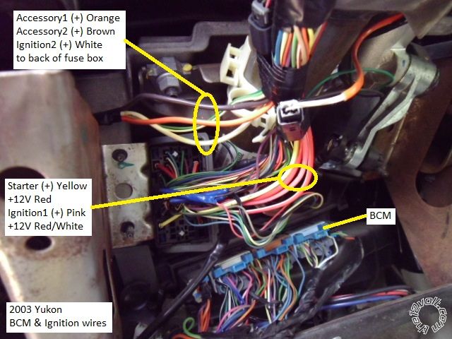
2003 2006 Gmc Yukon Remote Start Pictorial
What Is A Bypass Module And How Do I Wire It Up Youtube
