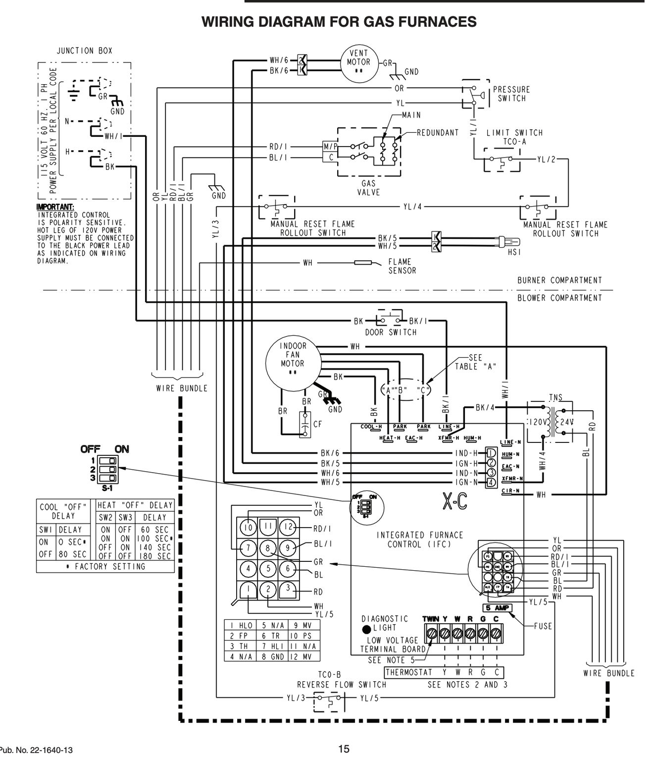
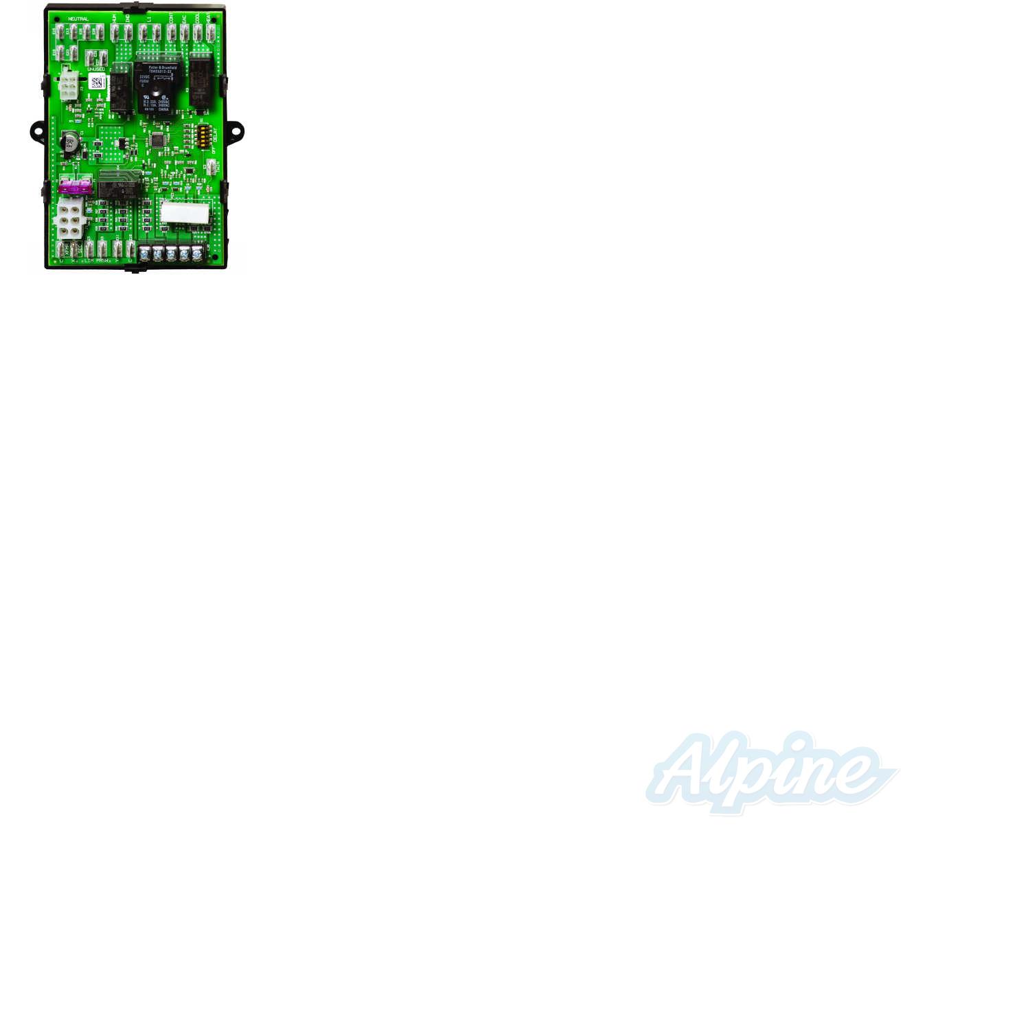
When installing the ST9120UB carefully check all appliance wires to make sure they are all connected to desired terminals at ST9120UB. The control board is the brain of your unit coordinating and executing the operation of other various components by sending voltage when and where needed.
Honeywell St9120u Wiring Diagram - If you're searching for picture and video information related to the key word you've come to visit the right site. Our website provides you with suggestions for viewing the highest quality video and image content, hunt and locate more informative video content and graphics that fit your interests. comprises one of thousands of video collections from various sources, particularly Youtube, therefore we recommend this movie for you to see. This blog is for them to stop by this website.
Fan Limit Switch Q A 5 Furnace Fan Limit Control Troubleshooting
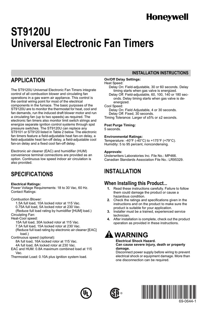
ST9120UB Universal Electronic Fan Timers.

Honeywell st9120u wiring diagram. Turn off power to. A control board is constantly monitoring sensors and safety switches in the unit. Use insulate wires of wire gauge at least AWG 24 for the interconnections.
Also on the circuit board the LED flashes so I know something isnt right. This control is the central wiring point for most of the electrical components in the furnace. Honeywell ST9120U 1011 universal electronic fan timer.
Keep the wires out of wires under line voltage ignition cable and other sources of electrical noise. Honeywell st9120u furnace control board honeywell how to install amp wire the fan amp limit controls on furnaces shop for honeywell furnace control on zoro com how to wire a honeywell thermostat hunker new honeywell r7284u to replace r7184b wiring question your home honeywell thermostat wiring lvtravelodge com honeywell thermostat wiring. It is approx 22 between the housings.
Wiring CAUTION Explosion or fire hazard. I used the wiring diagram for ST9160 system with SV95109520 SmartValve control. S8610U ST9120U S9200U Q3200U Universal Service Kit Promotion Distributors.
0ed7a Honeywell St9120u1011 Wiring Diagram Digital Resources. Ok can someone help me with the wiring diagram from a st9120c 4057 to a st9120u. Replaces 40 existing Honeywell electronic fan timers.
The basic purposes of the ST9120U are to monitor the thermostat for heat cool and fan demands run the. Honeywell Central Heating Wiring Diagram wiring diagram is a simplified welcome pictorial representation of an electrical circuitIt shows the components of the circuit as simplified shapes and the talent and signal contacts amid the devices. ST9120BU Wiring Conversion Instructions 1.
Honeywell Fan Control Board ST9120C 2002 ST9120C2002 No reviews yet Write a Review Write a Review. Setting Adjustable Heat Fan DIP Switches. Honeywell has replaced all their ST9120 series control boards with this universal control board kit which has wiring harnesess to be used with the furnace you are working on.
The wiring diagram provided by Honeywell does not address on which terminals the orange wires labeled 22 and 21 these leads went to the motor lead terminals on the original controller. This is a BRAND NEW OEM YORKLUXAIRECOLEMAN furnace Gas Valve Wiring HarnessThe YorkColemanLuxaire part is 024-31810-001 also S1-02531810001. ST9120U Wiring Connections with S8600 Intermittent Pilot Ignition.
I need a wire for wire to where every wire. None of their old ST9120 series boards are available so this kit. Be careful to directly connect to the new terminal with the same labeled identity or label each wire prior to removing from the original board.
Includes instructions and special wire harnesses for easy replacement. We need a wire to wire cross-reference for the controllers because we. Wiring CAUTION Explosion or fire hazard.
The ST9120U Universal Electronic Fan Timers integrate control of all combustion blower and circulating fan operations in a gas warm air appliance. Replaces all existing ST9101 ST9120 ST9141 and ST9160 fan timers and ST9150A 1003 ST9150B 2000 ST9150B 2018 ST9150B 2026 and ST9150B 2034 Ducane 20430801 and 28M99 Armstrong 45392-001 and 45692-001. Honeywell ST9120U 1011 electronic fan timer -.
Carefully remove each wire and connect directly to the corresponding loca-tion on the new ST9120U control board. Thought I had the wiring hooked up right but when I turn it on the blower turns on but the furnace does not ignite. Trying to replace original Honeywell ST9160B-1068 with ST9120U-1011.
Universal electronic fan timer replaces Honeywell ST9120 ST9101 ST9141 and ST9160 models installed in gas warm air furnaces. Wire lengths shall not exceed 5 m 15 ft. Honeywell Universal Control Board St9120u1011 Replaces Obsolete.
ST9120 to ST9120U Wiring Conversion Instructions 1. Incorrect wiring can lead to explosion hazard fire. Instructions included from Honeywell.
ST9120ST9101 to ST9120U Wiring Conversion Instructions. Both C and TWIN wires shall lead in parallel to each other. Using a three-wire hookup the protocol allows all EnviraCOM-enabled products in a system to speak to each other to maximize.
Honeywell offers a variety of on-site and web-based training options. When installing the ST9120U carefully check all appliance wires to make sure they are all connected to desired terminals at ST9120U. Appliance wiring compartment using the two 8 12-in.
Honeywell Furnace Control Circuit Board St9120u 1011 Ebay. Honeywell St9120u1011 Wiring Diagram Wiring Schematic Diagram. 5 Amp Control Board Fuse Keeps Blowing Help Hvac Diy Chatroom.
Turn off power to appliance. Incorrect wiring can lead to explosion hazard fire or equipment damage. And last but certainly not least the new ST9120U Universal.
Mount the ST9120U Electronic Fan Timer in the appliance wiring compartment using the two 8 12-in. Recommended Default Dip Switch Settings.
St9120u1003 Pdf Manualzz
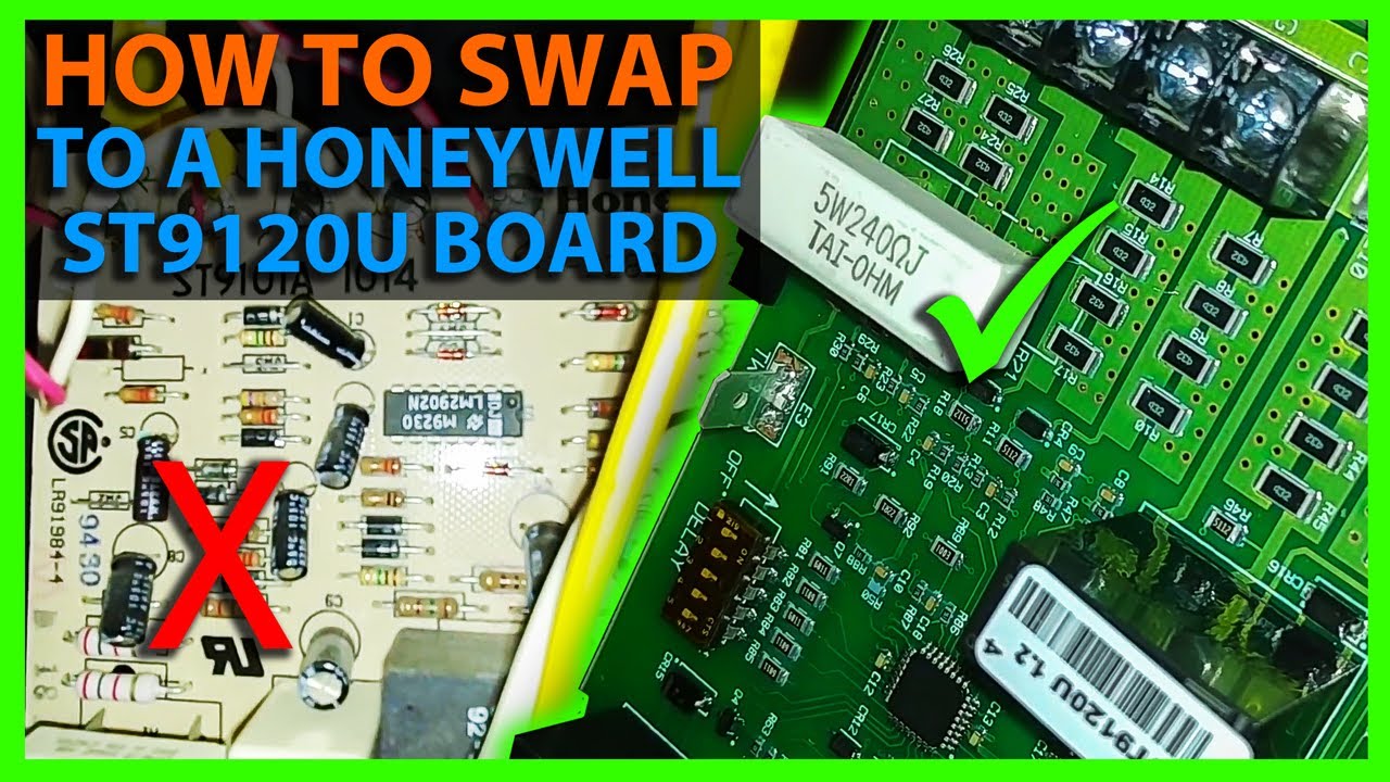
How To Install The Honeywell St9120u Furnace Control Board Youtube
Diagram St9120u Wiring Diagram Full Version Hd Quality Wiring Diagram Avdiagrams Fanofellini It
Honeywell St9120u1011 Universal Electronic Fan Timer Replaces Honeywell St9120 St9101 St9141 And St9160 Models
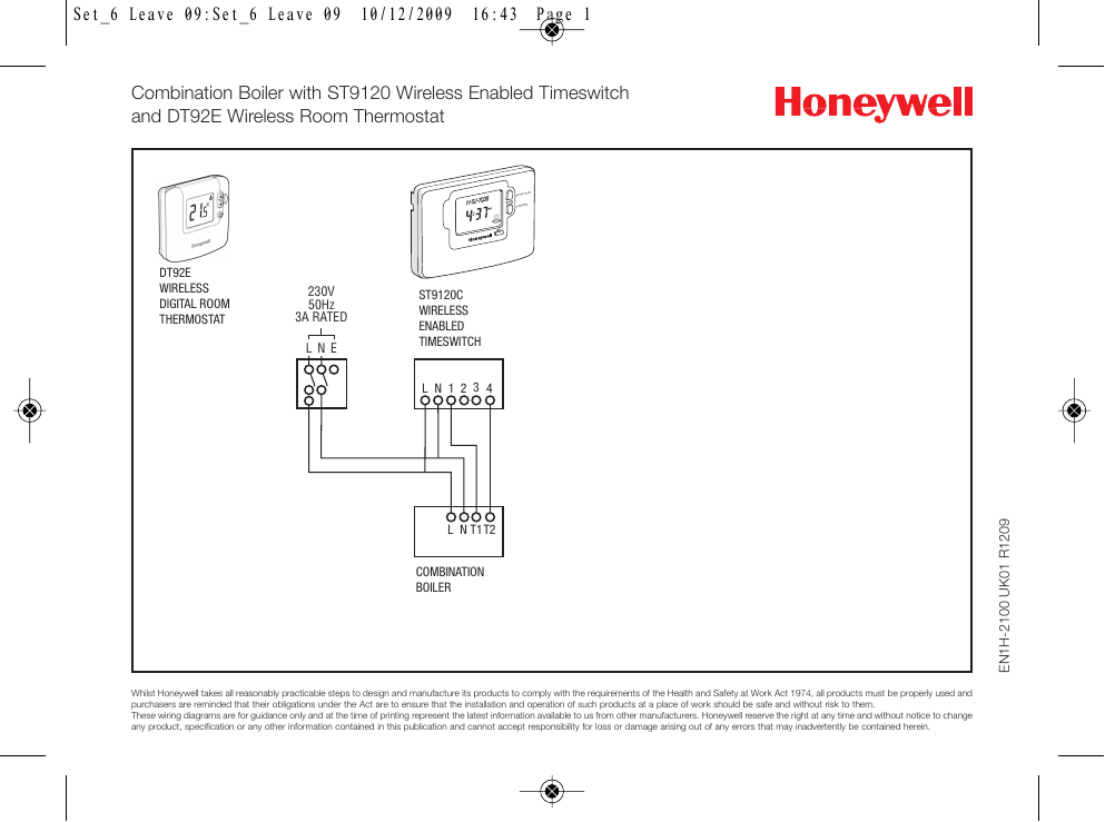
Faq Wiring Diagram Combination Boiler St9120 Manualzz

Fan Always Runs A C And Heater Never Do Doityourself Com Community Forums

Wiring Diagram Of Old Furnace Board With A New Furnace Board

Honeywell St9120c4057 Wiring Diagram Download Wiring Proposal Surat Tulisan

Wiring Diagram Of Old Furnace Board With A New Furnace Board
