13 Record the waveform of one of the wires below. ROTRONIC offers a comprehensive range of humidity instruments.
Rotronics Wiring Diagram - If you're searching for video and picture information linked to the key word you've come to visit the ideal site. Our website provides you with hints for viewing the highest quality video and picture content, hunt and locate more informative video content and graphics that fit your interests. includes one of tens of thousands of video collections from various sources, particularly Youtube, therefore we recommend this video for you to see. It is also possible to bring about supporting this site by sharing videos and images that you like on this site on your social media accounts like Facebook and Instagram or tell your closest friends share your experiences concerning the simplicity of access to downloads and the information that you get on this website. This site is for them to stop by this site.

Manual 4wd Chat Australia4wd Forum
M16 cable gland and screw terminals.

Rotronics wiring diagram. IP65 Corresponds to UL94-HB protection class. Rotronics Rda12 Battery Isolator Management Wiring Diagram Battery Charger Wiring Diagram Battery Isolator Battery Wiring Diagram 12v Dual Battery System With Isolator. I had a look and found a wiring diagram.
Heres that wiring diagram you asked for. The 6 BS cable is about 550 per Mtr and you need enough red and black to. Pick five resistors between 2K2 and 1M for Rb.
Rotronic Instruments UK Ltd. Calls may be recorded for training and quality purposes. You want a range of resistors that allow you to see Vce when the trnsistor is the saturated switch region and when it is in the active amplifier region.
Connect the positive wire coming from the circuit breaker to the terminal on the VSR marked RED. Regarding the maximum cable length use the following guidelines. Crompton Fields Crompton Way.
2 Sep 19 2007. Rotronic is a world leader in temperature and humidity measurement and known for the top quality and accuracy of its products. In a Landrover the other vehicle is your crumple zone For.
I have copied two links below for your reference which will explain how to wire up you charger with the option of jumpstarting the vehicle from the auxiliary battery. They used the trademark attorney firm Rotronics Pty Ltd to file this trademark. 2 3 Connect the thin - black.
One is marked main the other is marked auxillary. ABS Aluminium HF5xxS IP protection rating. Cable via hd fusible link from main battery to main terminal.
Connect - negative ground wire to the starting batterys negative terminal. ROTRONICS PTY LTD AUTOMOTIVE ELECTRONICS with trademark number 876188 was lodged on 18052001 and has a status of RegisteredProtected. 8mm bolts to connect the charge cables.
Cable via hd fusible link from auxillary battery to auxillary terminal. Joined Jan 3 2007. This wiring diagram illustrates that the 86 and 85 is the control circuit whereas 30 and 87 is the switch circuit.
Thanks to continuous expansion of its product portfolio Rotronic also offers products and solutions for measurement of the parameters differential pressure process pressure dew point and water activity in addition to temperature and humidity measuring instruments. The larger cable above is the minimum size required 6 BS 135mm² and matching lug note the wire above it thats the 6mm 459mm² Auto cable used by many to do the job its just not up to the task it at all. T 0121 514 0605 E email protected.
Use a 470R for Rc and a BC547 NPN transitor. Make sure your time is small enough so you dont have aliasing. Rotronics Battery Management Solutions Queen Street Darlaston West Midlands WS10 8JF.
Humidity measurement instruments featuring unique HygroClip digital technology and the most stable sensor in the industry. ROTRONIC offers a comprehensive range of humidity instruments. 2 -Wire or 34-Wire.
RS-485 USB LAN WLAN. Setup the following circuit on a bread board. Bin it get something better with comprehensive instructions and support from drivesafe.
Do not connect the positive wire at this stage left until last step. 1 Mount the circuit breaker under the bonnet close to the starting battery. Mini USB UART FDAGAMP compatibility.
On most of the units Ive installed the thin wire that isnt black red or yellow goes to an unswitched 12v Dave. Transmitters data loggers indicators probes sensors and humidity generators for the measurement and calibration of relative humidity dew point water activity and other humidity parameters. Humidity measurement instruments featuring unique HygroClip digital technology and the most stable sensor in the industry.
These are Australian made and a fairly complex product. The applicantowner of the trademark is registered as Rotronics Pty Ltd ACN. According to the diagram 30 is the negative terminal of the switch and 87 is the positive therefore it is the reverse in this course.
I will attempt to post the link and the diagram Rotronics RDA12. It is located under the bonnet on the passengers side and connected to the hydraulic Control Unit. If this cannot be avoided a shielded cable or a cable with twisted wires may be required to prevent interference due to electromagnetic induction.
Wiring Diagram VDC or Cabling Avoid running the cable connecting the unit in the same conduit as 110 VAC power cables. Sorry its so late ive just had a lot on my plate hahacheers bud. Transmitters data loggers indicators probes sensors and humidity generators for the measurement and calibration of relative humidity dew point water activity and other humidity parameters.
On the unit there should be two stainless steel bolts. FDA 21 CFR Part 11 and GAMP compatible. Rotronics parallel battery systems Rotronics has released a new range of 12 volt parallel battery management and 2 stage charge systems.
Describe where the wires are located.
Schematic Of The Wiring Diagram Location Of The Microcomputer And The Download Scientific Diagram
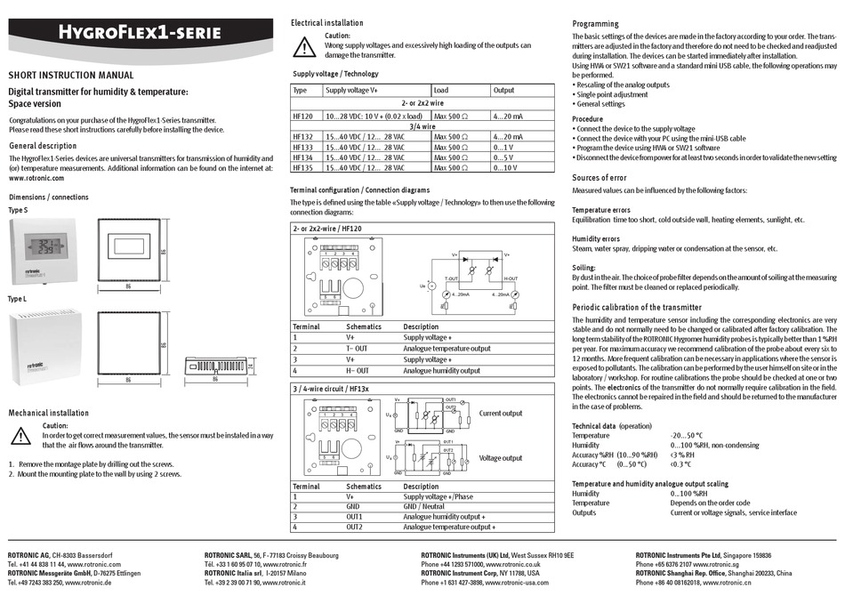
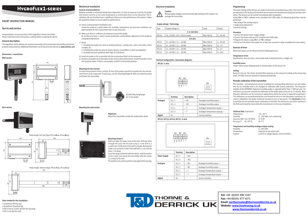
Rotronic Hf120 Instruction Manual Pdf Download Manualslib
Manual 4wd Chat Australia4wd Forum
Introduction Into The Rf System Of The Rms Rotronic
Rotronics Rda12 Battery Isolator Management Wiring Diagram

Manual 4wd Chat Australia4wd Forum
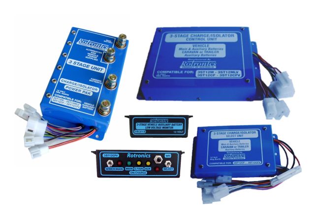
Rotronics Parallel Battery Systems
Rotronics Rda12 Battery Isolator Management Wiring Diagram
High Voltage Rotronic Ag
