The pressure sensor was mounted to the wheel housing with two sheet metal screws. Sensor Installation Boost Sensor Water Temp Sensor Oil Temp Sensor Exhaust Temp Sensor.
Apexi Boost Gauge Wiring Diagram - If you're searching for picture and video information related to the key word you've come to pay a visit to the right blog. Our website provides you with suggestions for seeing the maximum quality video and image content, search and locate more informative video articles and images that fit your interests. comprises one of tens of thousands of video collections from various sources, particularly Youtube, therefore we recommend this video that you see. You can also contribute to supporting this site by sharing videos and graphics that you like on this blog on your social media accounts such as Facebook and Instagram or educate your closest friends share your experiences concerning the ease of access to downloads and the information that you get on this site. This blog is for them to visit this website.

Apexi 403 A969 134 68 With Free Shipping At Andy S
Mechanical boost gauges can be operated by the compressed air alone but gauges at night will need to be lit in some way to be useful.

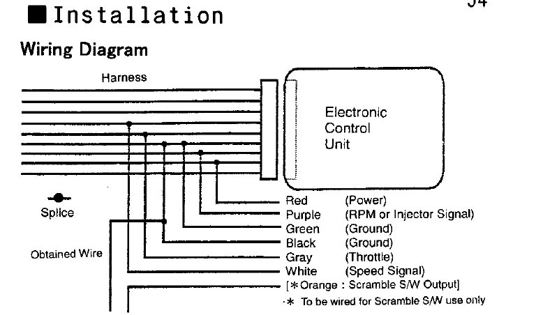
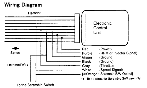
Apexi boost gauge wiring diagram. Peak Hold is also included in this function. Do not connect ohm meter to oxygen sensor or touch wire to ground or power. The vacuum line at the bottom of the photo leads to the APEXi pressure sensor and it has its own inline filter.
External wastegate setup shown below. Electrical Wiring Harness Diagram 2. Installation Procedures I.
The solenoid controls the air pressure provided to the precontrol and wastegate actuators thus allowing user control of boost. Instruction and installation manuals and information for JDM and other branded automotive electronics and parts. Wire the boost gauge using the radio as a path to the power and grounds needed to operate an electronic or digital boost gauge.
Apexi AVC-R ECU diagram Free download as PDF File pdf Text File txt or read Apexi Installation Instruction Manual. Now including AEM Apexi BeeR Billion Blitz Defi GreddyTrust HKS Perrin and Tein. Map sensor plumbing diagram.
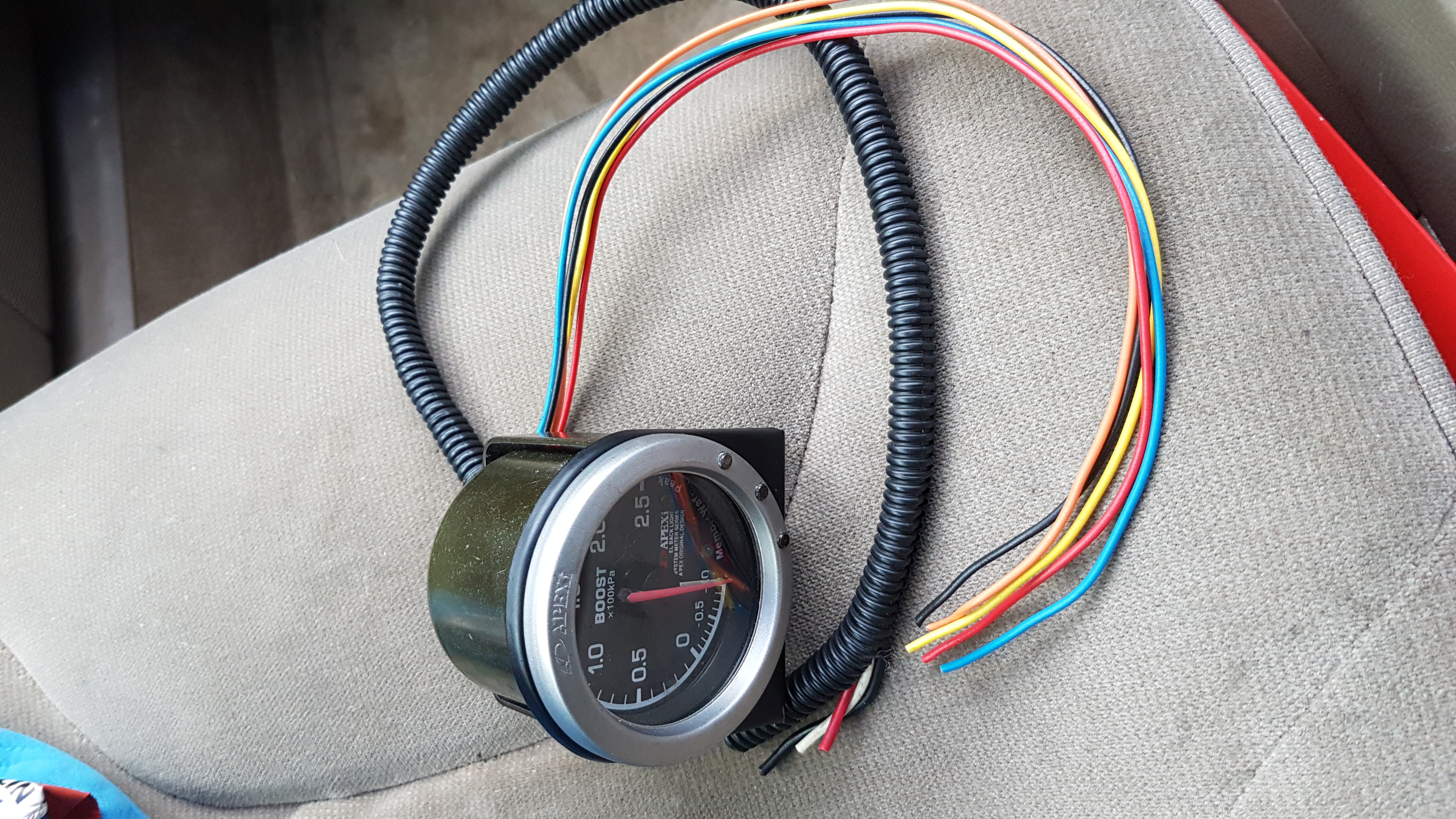
2Run a line from the bottom of the wastegate flange side to a feed from the boost system typically the little nipple on the turbo. Peel back some of the plastic covering to reveal the wires and give you space to splice into the wires. What youll need.
STEP 1 Install the Solenoid. Autometer Boost Gauge Wiring Diagram. -soldered every connection minus 2 crimps for the maf inout signal.
This product must be installed by a qualified automotive technician. Cut the line from step 2 and insert a T-piece and run a line to NC. You can tee the sensor together with a boost gauge.
Founded in Japan in 1992 APEXi has grown from just a small tuning parts manufacturer to a multi-industry international powerhouse. The illumination wire is shown below. Then strip your illumination wires for each of the gauges twist them together and crimp a female spade terminal to the end.
And thats all you need for the wiring. If air doesnt flow there is probably a problem. Ive just spent the day installing the Apexi AVC-R and playing with the Next you need to match up your wiring to the diagrams below by.
Pressure or VacuumBoost Gauge 1 Lamp socket 1 Light Bulb 1 VDO Mounting bracket from assembly or wiring diagram. Check for the connections to power ignition illumination and ground to wire a boost gauge for proper operation. After you have wired them in plug the connectors back in connect the head unit tidy up your wires etc and mount the unit Run a line from COM to the nipple on the actuator.
Apexi AFC Neo ECU Wiring Diagrams All Models Instructions Apexi AFC Neo Installation Manual Apexi AVCD Boost Controller Actuator Valve Controller Installation. GReddy E-Manage Wiring Diagram 30 kb - 13th Oct 2005 Greddy Profec B SPEC Instruction Manual 2620 kb - 30th Jan 2006. The boost controller is currently wired using the AEM wiring diagram I did not hook up scramble boost or the warning output aem-electronics-tru-boost-controller-gauge-electricaljpg I would ideally like to have boost-by-gear set up when the car is tuned but I believe it would have to be open loop since I am using the factory wheel speed sensors.
By using this custom algorithm the AVC-R can provide the ultimate boost curve to maximize traction and manal right out of the box. Sure that each wire has a secure connection. How to Install an Auto Meter Pro-Comp Ultra-Lite AirFuel Ratio Gauge - Electric on Your M or wiring diagram for your specific vehicle to learn which wire is the signal.
E Support Car 2 52mm Digital Turbo Boost Gauge Red LED. Ignore sensor type for now well cover that later. 2020 marks the 22 years for APEXi USA and the 28 years for the APEXi Group of Companies.
Apexi EL Series Boost Gauge Installation Manual 124 kb - 13th Oct 2005 Apexi AVC-R Boost Controller User Manual 1264 kb - 13th Oct 2005. A personal project by Rob at Odd Graphics. 1Run a line from COM to the top of the wastegate.
Growth has come from hard work research and the highest commitment to customer service and feedback. Use the boost gauge to read what pressure you are giving the sensor. To save a lot of writing Im just going to put this link in Manual or appexi boost setting.
Damage to oxygen sensor will result. The white cylindrical object is a filter on the line leading to the stock boost gauge sensor. It tells us that for the 90-94 Miata well use wiring diagram Z5-c.
RSM Rev Speed Meter Instructions. Next you need to match up your wiring to the diagrams below by splicing into the wire using scotch locks. A bike tire pump hooked in the vacuum line.
Mounting the Meter Control 3. Route the tube from the gauge to the engine. Cut the line from step 2 and insert a T-piece and run a line to NC.
Hookup Wiring the Gauge Illustration A. The Multi Mode displays up to two parameters in digital and one parameter in analog. If you blow through the solenoid NO or COM port you will feel a little resistance but air will flow.
The chart below is from the Apexi S-AFC wiring guide. Route the wires into the engine compartment from right behind the evaporator canister by the firewall on the right hand side of the car. April 7th 2019 - Turbosmart Dual Stage Boost Controller Wiring Diagram The wiring diagram on the opposite hand is particularly beneficial to an outside electrician Sometimes wiring diagram may also refer to the architectural wiring program The simplest approach to read a home wiring diagram is to begin at the source or the major power supply.
-disconnected the negative terminal. Then connect these two together. -made sure my red and redwhite wires were placed in correct order.
On the other end of your wire just crimp a male spade terminal.

Manual De Apexi Safc 2

2 52 Mm 7 Warna Led Mobil Minyak Temp Meter Gauge Asap Lensa Pointer Universal Mobil Meter Ad Ga52oilt Temp Meter Car Metercar Oil Aliexpress

1990 1994 Miata Apexi Super Afc Install Guide Mx 5 Miata Forum

Apexi El1 60mm Oil Pressure Gauge Wanted Uk Starlet Owners
Wiring Apexi Avc R To 90 93 Miata Turbo Forum Boost Cars Acquire Cats

The First Little Car Apexi Power Intake Pod Air Filter Hks Ssqv Bov Apexi Boost Meter Samco Hoses
Installing Apexi Avc R Need Wireing Help Rx8club Com
Oil Catch Can Apexi Boost Gauge Samco Hoses Starlet Parts For Sale Uk Starlet Owners
Oil Catch Can Apexi Boost Gauge Samco Hoses Starlet Parts For Sale Uk Starlet Owners
Related Posts
- Whole House Surge Protector Wiring Diagram A wiring diagram is a streamlined traditional pictorial depiction of an electrical circuit. Check all wiring for loose connections and shorting or b ...

- 60 66 Chevy Truck Wiring Diagram In brazil gm held on to their fuel injected version through the 1998 model year. This diagram is for large trucks but is similar to pick-up truck wi ...
- Nutone Intercom Wiring Diagram Pdf Connect 50 feet of 22 ga. Designed to update older intercom systems the dmc3 4 is a whole house music and communication system that uses your existi ...

- Paradox Alarm System Wiring Diagram Quick User Guide for Paradox Spectra SP Series SYSTEM MASTER CODE 1234 1 How to ARM the alarm system a How to do REGULAR ARMING the alarm system Hol ...
- Q68adi Wiring Diagram R35 Gtr Coil Wiring Diagram. 0 to 4000 Mitsubishi.Q68adi Wiring Diagram - If you're searching for video and picture information related to the ...
- Volvo Xc60 Wiring Diagram Volvo Xc60 2010 Wiring Diagram pdf manufactured by the company VOLVO presented for you in electronic format Page size 595 x 842 pts A4 rotated 0 deg ...
- Vw Beetle Fuel Gauge Wiring Diagram I wired the vibrator with black to the and the red jumper on the other vibrator terminal going to the left terminal on the fuel gauge. Dual Pro Char ...

