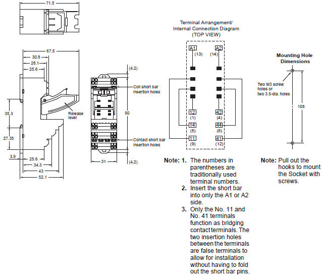
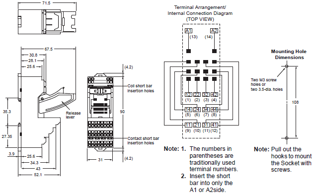
Page 6 295 max. To convert grams into ounces multiply by 003527.
Omron Pyf14a N Wiring Diagram - If you're searching for video and picture information linked to the key word you've come to pay a visit to the right site. Our site gives you suggestions for seeing the maximum quality video and image content, hunt and locate more informative video articles and images that match your interests. comprises one of tens of thousands of video collections from various sources, especially Youtube, therefore we recommend this movie that you view. This blog is for them to visit this site.
Pyf14a N Omron Relay Socket For Use With My4in My4in1 My4in1 D2 My4in Cr My4in D2 My4n My4n1 My4n1 D2 My4n Cr My4n D2 Rs Components
The PYF08A-E PYF11A-E and PYF14A-E have been approved as individual sockets by UL S08 and CSA C222.
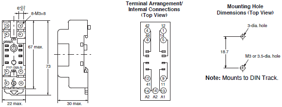
Omron pyf14a n wiring diagram. OMRON alldatasheet datasheet Datasheet search site for Electronic Components and. General-purpose Relay MY4N datasheet MY4N circuit MY4N data sheet. Electrical endurance will vary depending on the test conditions.
1-2-27 Shiromi Chuo-ku Osaka 540-6028 Japan Phone. The indicator is red for AC and green for DC. The Omron PYF14A-N is a 4-pole 14-pin Track Mounted Socket DIN railscrew mounting easy labelling quick connection with 3 coil terminals.
Long life minimum electrical operations. Relays with AC and DC coils have different colors of operating indicators LEDs. Front connecting socket with standard bifurcated contacts operation indicator built-in diode CR circuit used with MY series general purpose relays.
Xa 4281 Omron 4 Pin Relay Wiring Diagram 24vdc Socket Free My Datasheet Omron My2n D2 Dc24 Power Relay Dimension L W H 28 X 21 5 36 Mm Millimeter 343 Inr Piece Id C6838695. 14 pin relay wiring diagram 1975 280z 4 pole din surface mount base 4pdt 24vdc 5a terminals how to wire a socket rail pins 5 x pyf14a for cube my gs miniature power relays dimensions omron circuit diagrams of safety components dpdt my2n 240vac 24vdv cautions general purpose ge full h3y dc24 3h automation automotive or 3 what is its function types 12v dc coil non latching contactor my2nj eight use tutorial new original my4n 220 and 1no1nc plug in module fy pyf08a n. Built-in Ω.
OCTAL BASE GENERAL PURPOSE RELAYS. Releco C9-A41DC24V Relay 14PIN 5AMP 4POLE COIL 24VDC. Relay Division 28th Fl Crystal Tower Bldg.
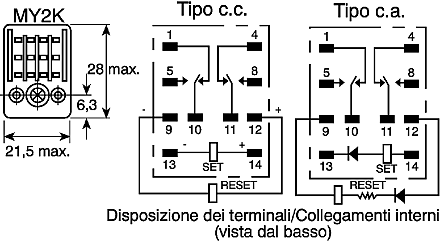
4 PYF14A-E PYF14A-N PY14 PY14-Y1 PY14QN PY14QN2 PY14QN-Y1 PY14QN2-Y1 PY14-02 Relay type Poles Front-connecting Socket DIN-track screw mounting Back-connecting Socket SolderWire-wrap terminals PCB terminals Socket Clip Socket Clip Socket Clip Without 2-pole test button 2 PYF08A-E PYF08A-N PYC-A1 PY08QN PYC-P PYC-P2 PY08-02 PYC-P PYC-P2 4 PYF14A-E PYF14A-N. 4 PYF14A-E PYF14A PYF14A-N finger protection PY14 PY14-3 PY14-Y1 PY14QN PY14QN-Y1 PY14-02 Note. MY2N DC Models AC Models Check the coil polarity when wiring and wire.
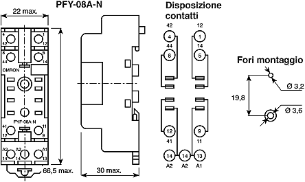
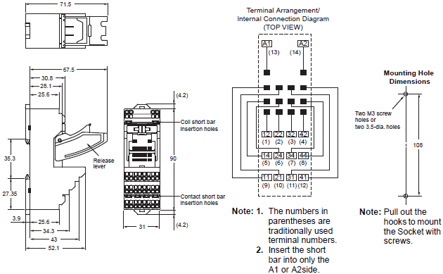
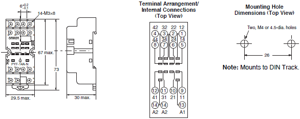
Solder terminal Wire-wrap terminal PC terminal H3YN-2-21 PYF08A PYF08A-N PYF08A-E PY08 PY08QN2 PY08-02 H3YN-4-41 H3YN-4-Z-41-Z PYF14A PYF14A-N PYF14A-E. PYF-14A-N 208 12 11 10 41 31 21 11 30 max. 1 x 1 415 max.
1Equipped with operation check terminal. The operation indicator indicates the energization of the coil and does not represent contact operation. 816-949-6134 ALL DIMENSIONS SHOWN ARE IN MILLIMETERS.
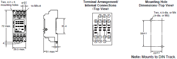
PYF14A-N Terminal Arrangement Mounting Holes for Surface Mounting 42 32 22 12 44 34 24 14 Two 35 dia. Mechanical operation indicators ar e a standard feature on all models. The PYF14A-N is a 4-pole 14-pin Track Mounted Socket DIN railscrew mounting easy labelling quick connection with 3 coil terminals.
Printing on the coil tape indicates the operating coil specification. The PYF14A-N is a 4-pole 14-pin Track Mounted Socket DIN railscrew mounting easy labelling quick connection with 3 coil terminals. Front connecting socket with standard bifurcated contacts operation indicator built-in diode CR circuit used with MY.
OMRON Corporation CC Components Division HQ. To convert millimeters into inches multiply by 003937. Something went wrong - please try again later.
1 pcs Relay Omron MKS2PI 24VDC Socket 2 pcs Accu 12 Volt Serie up 24V DC Sesuaikan TDR Berikut gambar rangkaian utama dan wiring diagramnya. Reduces wiring work by 60 when combined with the PYF-PU Push-In Plus Socket a ccording to actual OMRON measurements. Pyf14a E Omron Industrial Automation Relay Socket Front New Original My4n Gs 220 240vac And 24vdc Omron Intermediate Relay Omron H3ca A Wiring Diagram Wiring Diagram Timer Omron.
MY-GS Miniature Power RelaysDimensions OMRON Industrial Automation Indonesia. Front connecting socket with standard bifurcated contacts operation indicator built-in diode CR circuit used with MY series general purpose relays. Wiring and wire all connections correctly.
Make Offer - Omron Relay Socket 4 Pin 4 Pole 3A 250VAC PN PYF14A-E- Lot of 5 13 Omron G7L-1A-T AC200-240V Relay with P7LF-D DIN Rail Bracket for G7L C 6702 Automotive. Solder terminal Wire-wrap terminal PC terminal H3Y-2 PYF08A PYF08A-N PYF08A-E PY08 PY08QN2 PY08-02 H3Y-4 PYF14A PYF14A-N PYF14A-E PY14 PY14QN2 PY14-02 Rated time Time setting range Rated time Time setting range 05 s 004 to 05 s 3 min 01 to 3 min 1 s 01 to 1 s 5 min 02 to 5 min 5 s 02 to 5 s 10 min 05 to 10 min. Mounting Plates for Sockets Socket model For 1 socket For 18 sockets For 36 sockets.
My Gs Miniature Power Relays Dimensions Omron Industrial Automation
My Gs Miniature Power Relays Dimensions Omron Industrial Automation Vietnam
Pyf14a E Omron Twittlebit
My Gs Miniature Power Relays Dimensions Omron Industrial Automation
My Gs Miniature Power Relays Dimensions Omron Industrial Automation
Wiring Diagram For Omron Relay My4n
My Gs Miniature Power Relays Dimensions Omron Industrial Automation
My Gs Miniature Power Relays Dimensions Omron Industrial Automation
Pyf08a N Omron Relay Socket For Use With My2in My2in1 My2in1 D2 My2in Cr My2in D2 My2n My2n1 My2n1 D2 My2n Cr My2n D2 2 Rs Components
