The Casseta switch will only carry 6 amps of current while this relay will carry 20 amps. RIBRelay In A BoxFunctional De Enclosed Relay RIB Relay in a Box Series.
Rib2421b Wiring Diagram - If you're looking for video and picture information linked to the key word you have come to pay a visit to the ideal blog. Our site provides you with suggestions for seeing the maximum quality video and image content, search and locate more enlightening video content and images that fit your interests. comprises one of tens of thousands of movie collections from several sources, especially Youtube, therefore we recommend this movie that you view. This site is for them to stop by this website.

Rib2421b Rib Relay In A Box Functional Devices Enclosed Relay Galco Industrial Electronics
The Dry Contact Input RIB provides the low-voltage Class 2 power needed to activate the relay self-powered - just close the dry-contact input.

Rib2421b wiring diagram. One 1 SPDT Continuous Duty Coil RIB2421B One 1 SPST Continuous Duty Coil RIB2421SB 10 million cycles minimum mechanical-30 to 140 F 5 to 95 noncondensing 18ms LED On Activated 230 x 320 x 180 with 50 NPT Nipple 16 600V Rated UL Listed UL916 UL864 C-UL. From the Functional Devices website you can download RIB Relays Data Sheets Wiring Diagrams AutoCAD Drawings and Visio Drawings all in one place. Assortment of rib2401b wiring diagram.
This relay gives you a normally open or normally closed set of contacts. Here is the wiring diagram that is provided in the manual. Enclosed Relay SPDT 10A 10-30VACDC or 120VAC Coil.
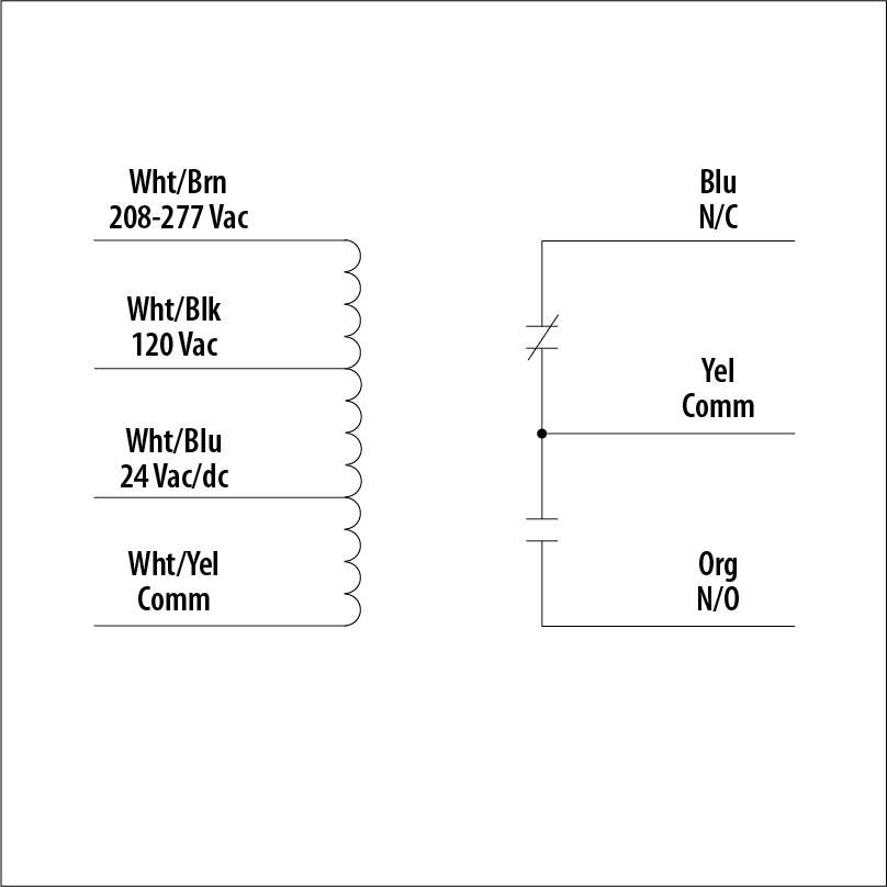
Enclosed Relay 20 Amp SPDT with 24 Vacdc120 Vac208-277 Vac Coil Made in USA UL Listed. One 1 SPDT Continuous Duty Coil 10 million cycles minimum mechanical-30 to 140 F 5 to 95 noncondensing 18ms LED On Activated 230 x 320 x 180 with 50 NPT Nipple 16 600V Rated UL Listed UL916 UL864 C-UL California State Fire Marshal CE RoHS. Rib2401b Wiring Diagram.
To install remove a conduit knockout in the equipment insert the wires and nipple through the hole tighten the locknut and connect the wires. As you research RIB relays transformers current sensors and power supplies make sure to take a look at the site. It is wired between the Lutron Casseta switch and the load.
The RIB Power Series has a protruding 12 or 34 NPT nipple from which all wires exit except T series. An RIB2421B is a relay in a self contained housing that could attach directly to your current receptacle box. The coil wires can connect to the receptacle and the low voltage switch lines are led out of the box for use.
So does this mean I can use a smart thermostat that runs off of 24 volts thinking Nest or Ecobee or do I need a line-voltage thermostat 240 volts. A wiring diagram is a type of schematic which uses abstract photographic icons to reveal all the interconnections of parts in a system. Made in United States.
The simplest way to do what you want is to use a relay. 10 amp dpdt 24 VACDC120 VAC coil sold as each Functional Devices RIB2401D enclosed pilot relay 10 amp dpdt with 24 VACDC120 VAC coil. Connect the three wires to the corresponding FANLED SENSOR IN-.
Wiring Diagram and Schematic Role Rib Relay Schematic November 20 2019 1 Margaret Byrd. It shows the parts of the circuit as streamlined forms and also the power and signal connections in between the devices. Electrical wiring diagrams are made up of two points.
RIB Power Series - 20 30A Relays The RIB Power Series has relay contacts rated for 20 and 30A. Remove the backing paper from the adhesive backed Fan Sensor and attach to the 1 furnace control mounting plate next to the furnace control module. Then you should know about a terrific resource on the Functional Devices website.
Just Whats Wiring Diagram. Functional Devices RIB2421B. According to the manual I can wire in an externalremote thermostat to the provided terminal station using 16 AWG wire.
Route the three wire cable along the same path as the thermostat wiring to the twinning control. The power to energize the relay can be brought to the relay on a separate pair of wires along with the control output of the controller or can be a. One 1 DPDT Continuous Duty Coil 10 million cycles minimum mechanical-30 to 140 F 5 to 95 noncondensing 18mS LED On Activated 400 x 400 x 180 with 50 NPT Nipple 16 600V Rated UL Listed UL916 UL864 C-UL California State Fire Marshal CE RoHS.
Fan Sensor Wiring Installation 1. One 1 DPDT Continuous Duty Coil 10 million cycles minimum mechanical-30 to 140 F 5 to 95 noncondensing 8ms LED On Activated 170 x 280 x 150 with 50 NPT nipple 16 600V Rated UL Listed UL916 UL864 C-UL California State Fire Marshal CE RoHS. A wiring diagram is a streamlined conventional pictorial representation of an electrical circuit.
It is somewhat complicated to wire but there are good instructions and when pared with the wiring diagram in the Casseta switch box it is possible to determine the proper wiring. Series RIB Relay in a Box Overview Documents. Functional Devices RIB RIB2421B Relay 24VACDC 120-277VAC 20A SPDT.
Signs that stand for the components in the circuit and also lines that stand for the links in between them. RIB2421B RIB2421B Functional Devices RIB Enclosed Relay 20Amp SPDT 24Vacdc120Vac208-277Vac Enclosed Relay 20Amp SPDT 24Vacdc120Vac208-277Vac 8774822236 Free shipping on most orders over 199. Manufactured by Functional Devices Inc.
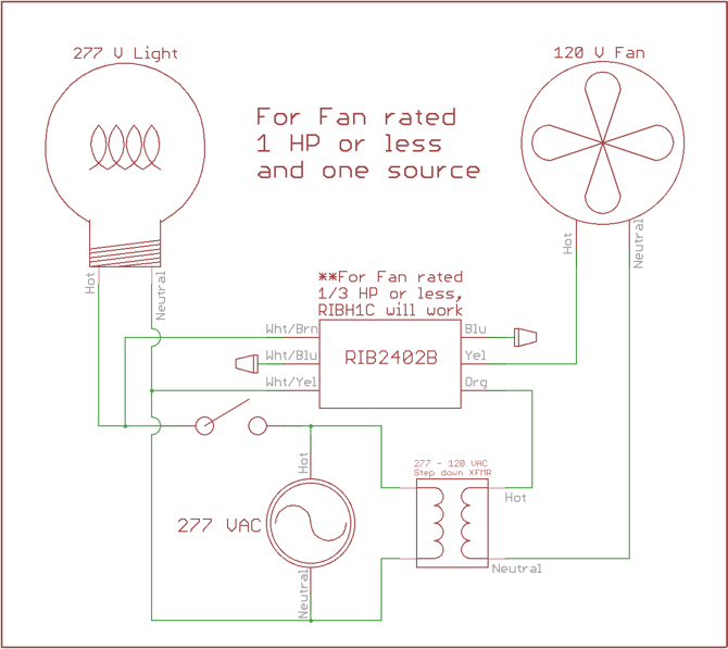
Using Rib Relays To Control Bathroom Fans Lights Functional Devices Inc

Details Functional Devices Inc
Https Www Functionaldevices Com Downloads Datasheets Rib2421b Pdf

17 Car Horn Relay Wiring Diagram Auto Mecanica Fiacao Eletrica Auto
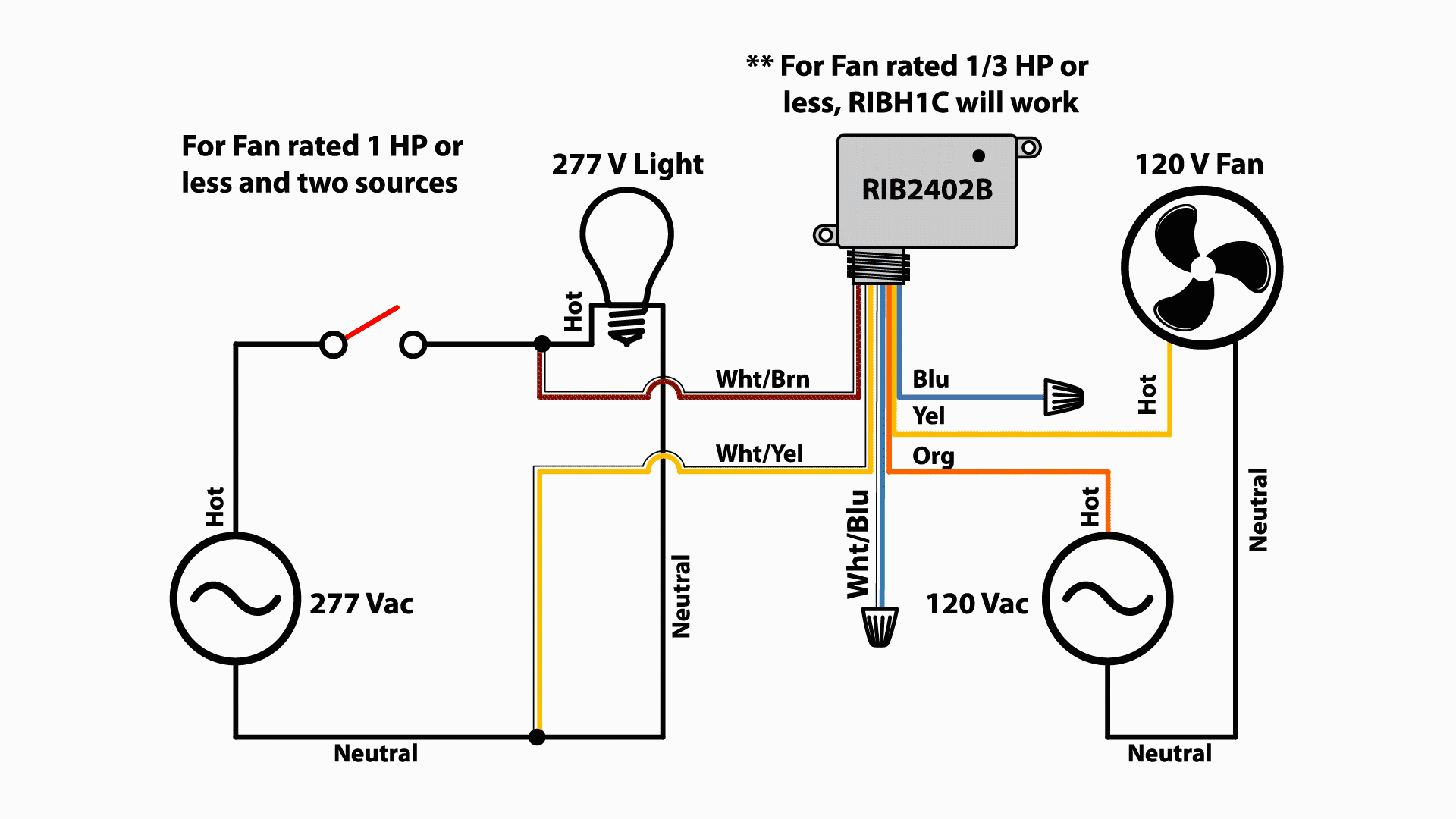
Using Rib Relays To Control Bathroom Fans Lights Functional Devices Inc
Details Functional Devices Inc

7500 Watt Garage Heater And Remote Thermostat Wiring Doityourself Com Community Forums
7500 Watt Garage Heater And Remote Thermostat Wiring Doityourself Com Community Forums

Details Functional Devices Inc
