2 Wiring diagrams. 21D83M-843 Replacement Kit for Lennox Single Stage Nitride Ignition lire le manuel dutilisation en ligne ou le télécharger au format PDF.
21d83m 843 Wiring Diagram - If you're searching for picture and video information related to the keyword you have come to visit the right blog. Our site provides you with hints for viewing the maximum quality video and image content, hunt and find more enlightening video articles and images that match your interests. includes one of thousands of video collections from several sources, especially Youtube, so we recommend this video for you to view. This blog is for them to stop by this website.

White Rodgers Furnace Fan Control Mccombs Supply Co 21d83m 843
1 50A66-843 ignition control board 1 Wiring harness 9-pin to 12-pin 1 Wiring harness 4-pin to 6-pin 1 Mounting panel 4 Stand-off fasteners 1 Circuit breaker 1 4 blue wire 2 Wiring diagrams.
21d83m 843 wiring diagram. 1 Wiring har ness 9-pin to 12-pin 1 Wiring har ness 4-pin to 6-pin 1 Mounting panel. Led Bulbs Hk42fz013 Upgraded Payne Furnace Control Circuit Board Electrical. 5 to 93 relative humidity non-condensing Timing Specifications.
2 - Wiring harness 9-pin to 12-pin 4-pin to 6-pin Mounting Panel. INJURY ANDOR PROPERTY DAMAGE. I am not a professional this is just for reference only.
Controls Gas Valve Ignitor Blower Inducer Humidifier and Air Cleaner. Change a wire connection on the unit transformer from 240V terminal to 208V terminal as shown on the wiring diagram. 1 Wiring harness 9-pin to 12-pin.
Replace the access panel. 1 4 blue wire 2 Wiring diagrams. Diagram bobcat 843 wiring full how wire a white rodgers room ruud furnace control for board 5 gas valve get universal hot surface thermostat 21d83m specification rogers 50a50 241 and nest circuit stopped working after burning smell diagrams c needed 50a51.
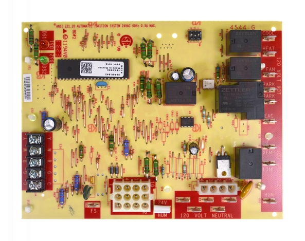
21D83M-843 simplifies installation and ensures peak system performance. Use only copper conductors. 1 50A66-843 Ignition Control Board.
1 Table 1 Wiring Diagram 5001-6973 24L8501 63K8901 97L4801 50A62-120 50A62-121 50A62-820 4 PROCEDURE 2 Figure 1 Picture 2 Table 2 Wiring Diagram 5001-6972 100925-01 100925-03 17W9201 23W5101 30W2501 69M0801 69M1501 83M00 21D83M-843 50A66-122 50A66-123 5 PROCEDURE 3 The 21D83M-843 kit will replace the following Controls. WARNING INSTALLATION CAUTION REPLACING 10M9301 12L6901 32M8801 50A65-120 50A65-121 or 56L8401 PROCEDURE 1 MOUNTING PANEL Arrow on front of panel. Integrated Single Stage.
Single Stage Nitride Ignition Integrated Furnace Control. If any of the original unit wiring is replaced the same size and type wire must be used. All times are in seconds unless noted otherwise 21D83M-843.
21D83M-843 - read user manual online or download in PDF format. 1 50A66-843 ignition control board. -40 to 175F -40 to 79C Humidity Range.
50A65-843 24 VAC 120 VAC 24 VAC CLASS II TRANSFORMER HOT LINE NEUTRAL LINE TH TR Low Voltage 24 VAC Line Voltage 120 VAC LEGEND N. Documenting how I replaced a new control board. Connections 13 39 Wiring Diagram 20 kW w PSC Blower Motor 30 19 Separate Thermostats Same Furnace 21D83M 843 Amazon Simple Storage Service April 4th 2019 - 21D83M 843 Integrated Single Stage Furnace Control Replacement Kit PRECAUTIONS INSTALLATION INSTRUCTIONS Kit includes 1 50A66 843.
1 50A66-843 Ignition Control Board 1 Wiring harness 9-pin to 12-pin 1 Wiring harness 4-pin to 6-pin 1 Mounting panel 4 Stand-off fasteners 1 Circuit breaker 1 4 blue wire 2 Wiring diagrams Replace the Original with the Original. 1 Wiring harness 9-pin to 12-pin 1 Wiring harness 4-pin to 6-pin 1 Mounting panel. 21D83M-843 simplifies installation and ensures peak system performance.
White Rodgers 21D83M-843 INSTALLATION CAUTION PROCEDURE 1. Affix wiring diagram 5001-6973 adjacent to the. Furnace Control Replacement Kit.
Normally open switch TYPICAL SYSTEM WIRING DIAGRAM The 50A65-843 is an automatic gas interrupted ignition control that employs a microprocessor to continually monitor. 1 50A66-843 ignition control board. 1 50A66-843 Ignition Control Board 1 Wiring harness 9-pin to 12-pin 1 Wiring harness 4-pin to 6-pin 1 Mounting panel 4 Stand-off fasteners 1 Circuit breaker 1 4 blue wire 2 Wiring diagrams Replace the Original with the Original.
If 208 Volt is supplied transformer connection must be changed SINGLE PHASE POWER SUPPLY GROUND LUG. Existing unit wiring diagram. INST ALLA TION INSTR UCTIONS.
1 - 50A66-843 Ignition Control Board. White Rodgers 50A55-843 on Amazon. 1 50A66-843 Ignition Control Board 1 Wiring harness 9-pin to 12-pin 1 Wiring harness 4-pin to 6-pin 1 Mounting panel 4 Stand-off fasteners 1 Circuit breaker 1 4 blue wire 2 Wiring diagrams Replace the Original with the Original.
INSTALLING OR OPERATING THIS CONTROL COULD CAUSE PERSONAL. Heat delay to fan ON 45. White-Rodgers-21D83M-843-Users-Manual-162382 white-rodgers-21d83m-843-users-manual-162382 21D83M-843 to the manual 96996983-b99a-4063-8897-39308c91a9b2.
This item is Brand New In the Package and Unused. Up for sale is a White-Rodgers part number 21D83M-843. Normally closed switch N.
FAILURE TO READ AND FOLLOW ALL INSTRUCTIONS CAREFULLY BEFORE. Controls Gas Valve Ignitor Blower Inducer Humidifier and Air Cleaner. White Rodgers 21D83M-843 Furnace User Manual.

White Rodgers 21d83m 843 Installation Caution Procedure 1

Integrated Furnace Controls Direct Oem Replacement White Rodgers

21d83m 843 White Rodgers 21d83m 843 Single Stage Hsi Integrated Furnace Control Kit

Lennox Y7761 Integrated Furnace Control Board Kit Technical Hot Cold
21d83m 843 Emerson White Rodgers Surelite Ignition Board Hot Surface Ignition Lennox Amre Supply

White Rodgers 21d83m 843 Specification Manualzz

21d83m 843 White Rodgers 21d83m 843 Single Stage Hsi Integrated Furnace Control Kit
21d83m 843 Emerson Climate Technologies

21d83m 843 White Rodgers 21d83m 843 Single Stage Hsi Integrated Furnace Control Kit
