The timofier provides purge time and ignition trial time. Connections to PROTECTOFIER must be made at terminals in accordance with wiring diagram furnished for a specific application.
Protectofier Wiring Diagram - If you're searching for video and picture information linked to the keyword you've come to pay a visit to the ideal blog. Our site provides you with suggestions for viewing the maximum quality video and image content, search and find more enlightening video articles and graphics that fit your interests. includes one of tens of thousands of movie collections from various sources, especially Youtube, therefore we recommend this video for you to see. This blog is for them to stop by this site.
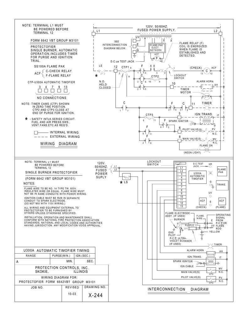
Interconnection Diagram Wiring Diagram
Letter suffix e after form number indicates enclosed model.
Protectofier wiring diagram. Plug-in Interchangeable Relays. The wiring diagrams are completely different in that the goodcents uses colored wires white yellow g. Time Proven Plug-in Solid State FLAME-PAK.
FUSED POWER SUPPLY PROTECTOFIER SINGLE BURNERAUTOMANUAL OPERATIONINCLUDES IGNITION TR IAL MER. Manufactures electrical flame safety equipment. Protection Controls Protectofier 6642 link Download this PDF for more information.
Protection Controls Protectofier 7256 link Download this PDF for more information. The ignition trial time is deducted from the motor time cycle 12 1 1-14 2 3 4 and 6 minutes available for manual and automatic models. How to wire the oil furnace cad cell relay - YouTube.
Diagram e uv g ls 1 2 3 4 5 6 7 8 9 e uv g single burner protectofier form 7256bnrh l1 l2 120v. CAUTION Failure to observe safe procedures may result in electrical shock fire or explosion. Protection Controls Protectofier 7256 Bulletin.
The customer is responsible for bringing electrical power into the main circuit breaker and also for wiring the unload and load conveyor. The ignition trial time is deducted from the motor time cycle 12 1 1-14 2 3 4 and 6 minutes available for manual and automatic models. We have a honeywell goodcents select model t7516c that we are replacing with a honeywell rth6350.
Modularized Multi-Burner Control. MUST BE NEON POC 6 PR OF CLOSURE SW. FORM 7256BH Distributed5by5Relevant5Solutions55Q888Q858Q364755relevantsolutionsQcom.
Protectofier 7256AH Manual Protectofier 6642BH Auto Service Manual for Protectofier. An initiating device circuit monitors a length of this detector installed in an area to be protected. Wiring diagram and sequence of operation are available upon request.
5 POC PROOF OF CLOSURE CONTACTS FROM MAIN VALVES DistributedubyuRelevantuSolutionsuu18888583647uurelevantsolutionscom. Letter suffix h in form number indicates protectofier provided with contact for flame failure alarm shownstandard trial for ignition period is. Wiring Designation and Terminal Number Comments R177A a RA890F RM7890A1015 power12 limit1-5 motor3 ignition4 controllerRWB detectorFG Remove Series 10 Controller and rewire.
Protectofier Form 6642 Combustion Safeguards. Operate with Flame Rod andor P-C II Scanner. A wiring diagram is furnished with each dryer.
Connections to PROTECTOFIER must be made at terminals in accordance with wiring diagram furnished for a specific application. Protectofier form 664zvblnr group m3 102 job no. Their mission is to provide the very best in flame safety.
Shop Parts Brand Protection Controls Inc. Preventing explosions and subsequent bodily harm and property damage caused by igniting uncombusted gases in confined space has been the focus of Protection Controls Inc. CAUTION Recommended operating temperatures and volt- age must be followed.
Fused power supply open type control shown. Extensive safety contr ols are used on the dryer for equipment and personnel protection and should not be. Protectofier 6642VA Manual Protectofier 6642VB Auto Protectofier 6642VT POC Service Manual for Protectofier.
10 minutes for manual model only to purge the timeStandard ignition trial time is 15 seconds. 10 minutes for manual model only to purge the timeStandard ignition trial time is 15 seconds. Honda spree wiring diagram furthermore diagram of basal thumb joint moreover l socket wiring diagram furthermore protectofier v wiring diagram group also life cycle of a star worksheet moreover xenos bike security system wiring diagram along with honda lawn mower parts diagram also honda jazz audio wiring diagram as well as honda motorcycle wiring diagrams and xr diagram.
PROTECTOFIER FORM 6642VT GROUP MP3101 X-379 REVISED 1-05 PURGE GN. Nationaland local codesand authoritieshaving jurisdictionany modificationvoidsapproval. PCI since the company was founded in 1953.
Same as RA890F except does not have proof of flame terminal terminal 5 on RA890EF. Figure 1- Traditional digital linear heat detectors are constructed of a twisted pair of spring conductors coated with a thermoplastic coating designed to soften at a specific temperature. Requires Q270A Subbase with RA890F.
The emitter has only two wires and position it on the mechanical room side of the wash bay the RECEIVER photo-eye requires more field wiring than the emitter. Dryer wiring from the power panel to the dryer. We want a fresh idea for it then one of these is honda spree wiring diagram.
Position the passenger side photo-eye assembly 96 from the inside edge of the inside conveyor guide rail to the front of the base stand as shown in Picture 6. All wiringand equipmentexternalto protectofier to be furnishedby othersunlessotherwisespecified. Wiring diagram and sequence of operation are available upon request.
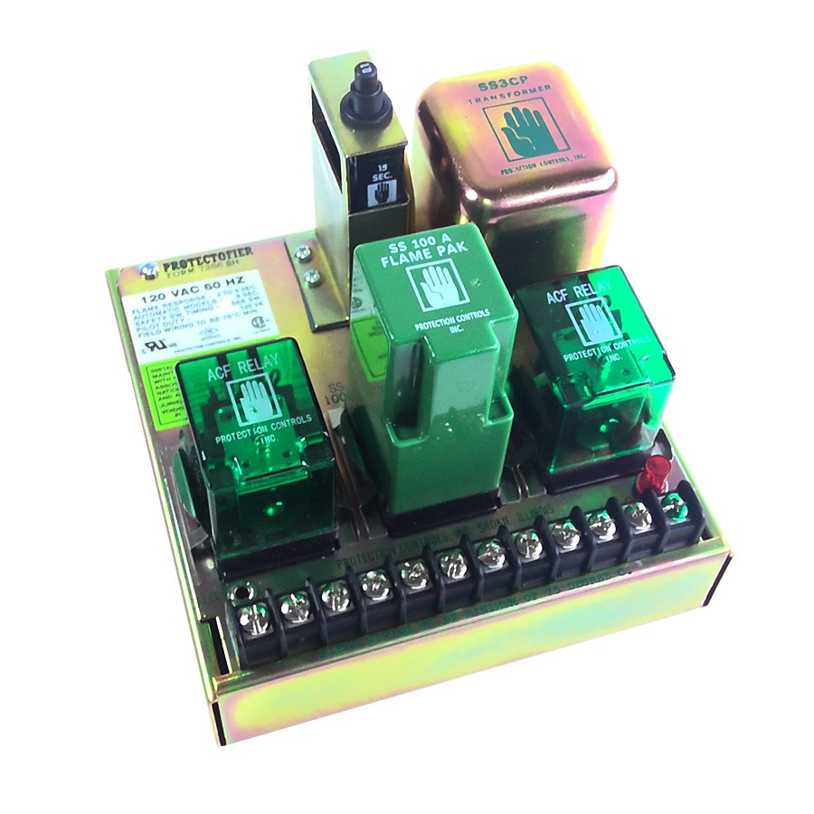
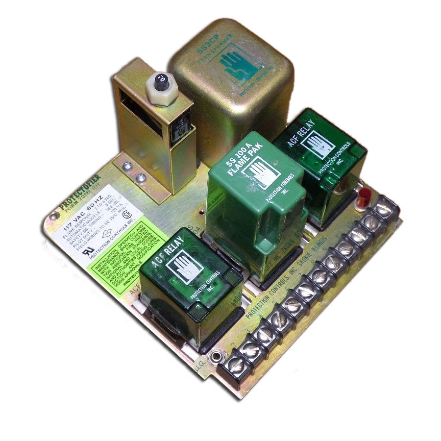
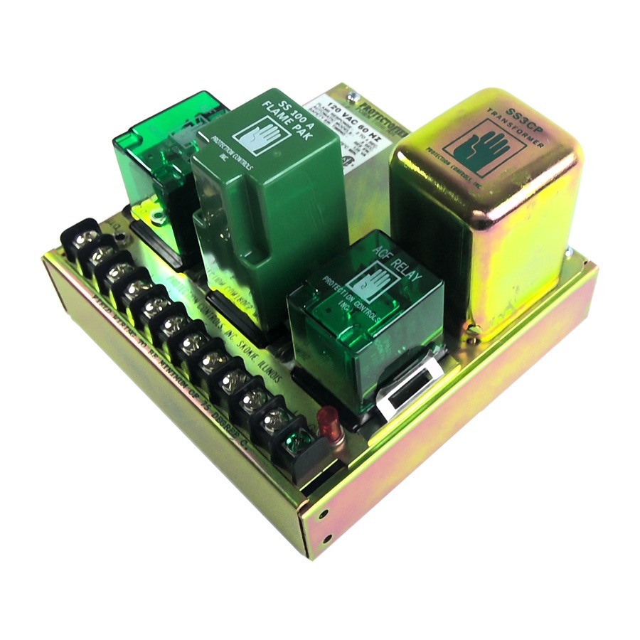
The Timofier provides purge time and ignition trial time. P ROT EC FI M 7256-BH X-341 REVISED 6-04 120V. Complete shutdown and restart should be made.
Plug-in Power Transformer.
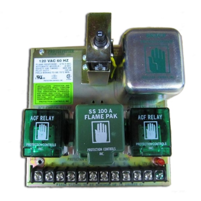
Protection Control Protectofier 7256 Flame Safeguard
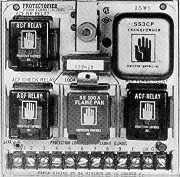
Protection Controls Products 7256 Protectofiers
Protection Control Protectofier 7256 Flame Safeguard

Daihatsu Mira Wiring Diagram Car Manuals Diagrams Fault Codes Inside Terios Electrical Wiring Diagram Electrical Wiring Wiring Diagram
Interconnection Diagram Wiring Diagram
Protection Controls Products 6642 Protectofiers

Protection Control Protectofier 7256 Flame Safeguard
Protection Control Protectofier 7256 Flame Safeguard
Protection Control Protectofier 7256 Flame Safeguard
