They are intended as aids to help explain the installation operation programming and use of the MELSEC System Q modules. High speed DC input module positive common type QX40H QX70H.
Qx40 Wiring Diagram - If you're looking for picture and video information related to the keyword you've come to pay a visit to the ideal blog. Our site gives you hints for seeing the highest quality video and image content, hunt and find more informative video articles and graphics that match your interests. includes one of tens of thousands of movie collections from various sources, especially Youtube, so we recommend this movie for you to see. This blog is for them to stop by this site.
Mitsubishi Electric Qx40 Manuals Manualslib
Loosen or missing screws.

Qx40 wiring diagram. Analog Input Type Q64AD. For up to date sales. High speed DC input module negative common type QX80H QX90H.
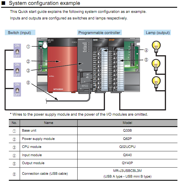
MITSUBISHI ELECTRIC Global website. Servo amplifier Servo motor MR-J4-B HG-SR Motion CPU Safety signal module IO module Q172DSCPU Q173DSXYQX40QY40P Shut-off Function Ensuring safe speed for area where people works Issue 2. Voltage drop at ON 02 V at 01 A 01 V at 05 AAlways insert the module fixing latch of the module into the module fixing hole of the base unit.
Speed up control by catching the input signal variation at 0 ms 3. Remote controller OnOff button Centrally Controlled. Please note some product models not sold in Indonesia may be included in the following manual s for our global customers.
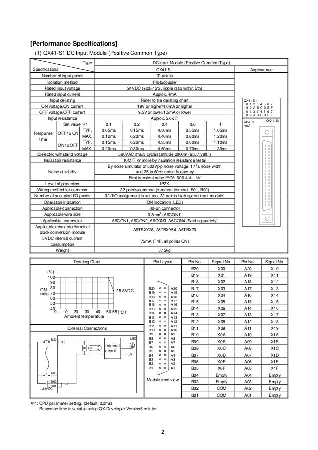
QX72 DC Input Module Positive CommonNegative Common Shared Type 37. QX80 DC Input Module Negative Common Type 38. Before After 2 When the indicator pops out wiring is complete.
Some products are regionally specific. Visit site to download your INFINITI vehicles manuals and guides and access important details regarding the use and care of your particular model year. Wiring method for common 32 pointscommon common terminal.
Fuel system conventional type system 13a pwee9007-abcdefgpdf fuel system comventional type sistem 13a pwee900. Buka program PLC New Project pilih type PLC. 16 point 24 VDC input 4mA sink type 16 pointscommon.
Two devices with differing power systems can be connected to the same module using different 8. Wiring diagram of CN51 Volt free contact Z is used to switch. Eliminated conventional maintenance job by the screw-less design.
Bar terminal 1 Push in a wire. 2Sebelum melakukan pemograman pada PLC terlebih dahulu melakukan setting IO Assignment sesuai pada Modul PLC. The MELSEC Series takes control to the next level.
The texts illustrations diagrams and examples in this manual are provided for information purposes only. Fuel system variable venturi carburetor. Minimized wiring time by the simple push-in structure.
Forcing the hook into the hole will damage the module connector and module. To call it backwards is value judgment. DrEng Syahril Ardi ST MT Sirin Fairus STP MT Sekar Sukmaningrum.
The QX40 has PNP transistors to accept inputs from NPN transistors. DIf a voltage ripple occurs during input or there is electrically induced noise on the external wiring connect a smoothing capacitor of 01 to 047 μF 25V. Enhanced solutions are realized by a wide lineup of PLCs and network systems.
View online or download Mitsubishi electric QX40 User Manual. B01 B02 Number of occupied IO points 32 IO assignment is set as a 32 points high speed input module Operation indication ON indication LED Applicable connection 40-pin connector Applicable wire size 03mm2 A6CON1. MELSEC Series PLCs always meet your system demands and more with something to offer for any prospective control system.
It is recommended to select Save from the right-click due to large size of manual PDF data. Fuel system electronic carburetor 13c pwee9007_abcdefgpdf fuel sistem. Mitsubishi electric QX40 Pdf User Manuals.
Input Tegangan terdiri dari beberapa yaitu 0 10V 0 5V 1 5V dan -10 -10V. This cable should be wired separately from power lines or any other lines which may induce electrical noise. Disain Sistem Kendali dan Monitoring Proses Instalasi Pengolahan Air Limbah Buangan Boiler Berbasis PLC dan HMI Human Machine Interface Penulis.
Mitsubishi calls it a sinking module because it accepts a sinking output from a sensor etc. Diagram of the indoor unit input and output CN32 CN51 and CN52 are normally used for inputs and outputs. The manual which name begins with Instruction Sheet is a simplified manual supplied with the product.
OFFDo not touch the conductive orelectronic parts of a module directly. Wiring diagram of CN32 Volt-free contacts X and Y are used to switch OnOff the indoor unit level signal. Safety Signal Wiring Step1 Step2 System Structure Settings Step3 Parameter Settings for Safety Observation Function PLC CPU GOT Main base unit Q06UDEHCPU GOT 1000 series Q35DB.
WIRING cThe analog input is received through a twisted pair shielded cable. Setting Parametter pada PLC. QX81 DC Input Module Negative Common Type 39.
As Duffanator says this is different from Allen-Bradley. Wiring connections can be easily confirmed. If you have any questoni s about the.
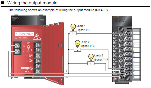
Impervious to vibration secured wiring connections. Output specifications for IO combined modules.
Rms Www Tstechgroup Com

Plc Prog Remote Control Training Servo Diagram

Q Series Dc Input Module Positive Common Type Qx41 Manualzz

Qx40 Mitsubishi 132572 16 Point 24vdc Input Bpx
Https Library Mitsubishielectric Co Uk Pdf Download Full 2242
197e
Rms Www Tstechgroup Com

Pdf New Product Release Q Series Dc Input Module Positive Common Type Qx41 S1 Qx42 S1 Soldering Type 40 Pin Connector A6con4 Nick Yuangga Academia Edu
