Analog Input Module Simatic Et 200sp Preface Doentation Guide 1 Product Overview Wiring Up 3 Hart Function Pdf Free Siemens Et200sp Selection Guide Awc Inc Analog Input Module Ai 4xi 2 4 Wire St 6es7134 6gd01 0ba1. SM 1231 analog input modules - Industry Mall - Siemens WW.
Siemens Analog Input Module Wiring Diagram - If you're looking for picture and video information related to the key word you've come to visit the ideal site. Our website gives you suggestions for viewing the maximum quality video and picture content, search and find more informative video articles and images that match your interests. includes one of tens of thousands of video collections from several sources, especially Youtube, therefore we recommend this movie for you to see. It is also possible to contribute to supporting this site by sharing videos and images that you like on this blog on your social networking accounts such as Facebook and Instagram or educate your closest friends share your experiences concerning the simplicity of access to downloads and the information that you get on this site. This blog is for them to stop by this site.

6es7331 7kf02 0ab0 Ai Wiring Entries Forum Industry Support Siemens
Wiring up 31 Wiring and block diagram Analog input module AI 8xI 2-4 -wire BA 6ES7134-6GF00-0AA1 Manual 032015 A5E34941201-AA 11 Connection.

Siemens analog input module wiring diagram. They are important components in a holistic industrial security concept. You can find information on wiring the BaseUnit in the ET 200SP distributed IO system. Analog Input Module AI 8xUI HF 6ES75317NF00- -0AB0 Manual 092016 A5E36649087-AB 23.
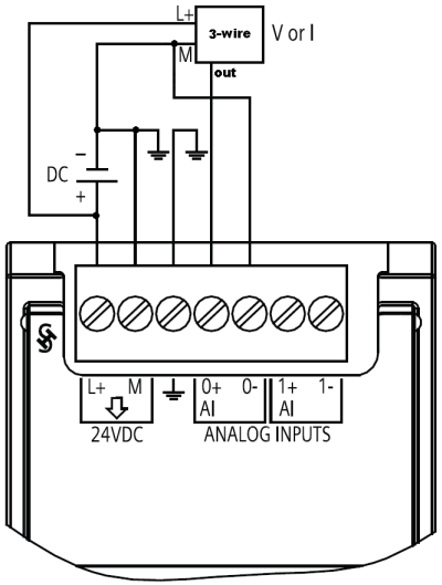
Functions that generally relate to the system are described in this manual. How to Wire a SIMATIC S7-1200 Analog Input Module AWC Inc. How to Wire a SIMATIC S7-1200 Analog Input Module AWC Inc.
The channels 0 to 3 of the module are copied in up to 4 submodules with configuration 1 x 4- channel module Module-internal shared input MSI. Functions that generally relate to the system are described in this manual. Hope this will help you.
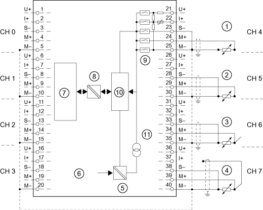
Also the order code of your module will tell us that either you have to do the Analog input setting in soft format or also do on the module. Block diagram and terminal assignment for 4-wire transducer for current measurement. Use a resistor across the current signal wiring appropriately to the PLC analog input terminals.
Analog input module AI 4xTC HS 6ES7134-6JD00-0DA1 Manual 032019 A5E42405270-AB Preface Guide to documentation 1 Product overview 2 Wiring 3 Parametersaddress space 4 Interruptsdiagnostics alarms 5 Technical specifications 6 Parameter data records A Representation of analog. I have never seen a 2 wire current sensor wired this way before. Current measurement 2-wire connection The following figure shows the block diagram and an example for the terminal assignment of the analog input module AI 8xI 2-4-wire BA on the BaseUnit BU type A0A1.
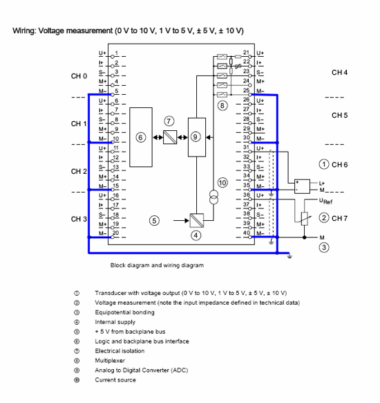
Analog input module AI 8xUIRTDTC ST 6ES75317KF00- -0AB0 6 Manual 072014 A5E03484864-AC Documentation guide 1 The documentation for the SIMATIC S7-1500 automation system and the SIMATIC ET 200MP distributed IO system is arranged into three areas. Address space for configuration as 1 x 4-channelAI 4xUIRTDTC ST MSI. The example in the following figure shows the pin assignment for current measurement with 4-wire transducers.
Analog Input Module AI 4xI 2wire 420mA HART 6 Manual 112014 A5E35098013-AA Security information Siemens provides products and solutions with industrial security functions that support the secure operation of plants solutions machines equipment andor networks. Use the correct value for range configured in your PLC analog input module remember to download the hardware configuration to the PLC after any module configuration changes - something I sometimes forget. In the manual when looking at the wiring diagram for 2 wire current connection it seems to me that they are saying to simply wire the 2 wire sensor directly into the module with out any power supply to the current loop as I would normally expect for a 4-20ma 2 wire configuration.
Analog Input Module AI 4xUIRTDTC ST 6ES75317QD00- -0AB0 Manual 092014 A5E32366209-AB 33. This arrangement enables you to access the specific content you require. This manual have the wiring diagrams of each standard Signal module of S7-300 series.
Analog input module AI 2xI 24-wire ST 6ES7134-6GB00-0BA1 Manual 042018 A5E36104399-AB Preface Documentation guide 1 Product overview 2 Wiring 3 Parametersaddress space 4 Interruptsdiagnostics alarms 5 Technical specifications 6 Parameter data record A Representation of analog. This section provides the block diagram of the F-AI 4xI 0420mA 2-4-wire HF analog input module with the terminal assignment. Analog input module AI 8xU BA 6ES71346FF00- -0AA1 10 Manual 032015 A5E34941660-AA Wiring up 3 31 Wiring and block diagram This section includes the block diagram of the AI 8xU BA module with the terminal assignments for a 2-wire connection.

Profibus Connector 6es7331 1kf02 0ab0
Https Support Industry Siemens Com Cs Attachments 59193205 S71500 Ai 8xu I Rtd Tc St Manual En Us En Us Pdf Download True

Pin On Fred
How Do You Connect A Sensor To The Analog Signal Modules Of The S7 1200 S7 1500 An Id 40913432 Industry Support Siemens

Analog Input Module Sm 331 Ai 8 X 13 Bit 6es7331 1kf02 0ab0 Simatic S7 300 S7 3 Id 8859629 Industry Support Siemens
With The Correct Wiring How Can You Avoid Exceeding The Common Mode Voltage Ucm Id 11966082 Industry Support Siemens
Https Support Industry Siemens Com Tf Ww En Posts Wiring Potentiometer To Analog Input Output Module Ai 4xu I Rtd Tc Aq 2xu I St 6es7534 7qe00 0ab0 180054

Sinking And Sourcing Digital Input Modules Digital Wiring Diagram Diagram
Analog Input Module Sm 331 Ai 8 X 13 Bit 6es7331 1kf02 0ab0 Simatic S7 300 S7 3 Id 8859629 Industry Support Siemens
