That changed when they went over to G1000 installations and all aircraft were built to a common standard. The 13AWG wires power rejection is one-.
Avionics Wiring Diagrams - If you're searching for picture and video information linked to the keyword you have come to visit the ideal site. Our website provides you with hints for viewing the maximum quality video and picture content, search and find more informative video articles and graphics that fit your interests. includes one of tens of thousands of movie collections from several sources, particularly Youtube, therefore we recommend this movie for you to view. This site is for them to stop by this site.
Aircraft Electrical
Beechcraft used to provide a customised avionics wiring diagram with each aircraft.

Avionics wiring diagrams. Document and review all aspects of your electrical system. These drawings are a tremendous value. ConfigurationConfigure all of the avionics in the aircraft.
Aircraft wiring diagram software A Newbie s Overview of Circuit Diagrams. Bonanza and Baron owners often still have the blue folders. If you have us wire your harnesses we will include a schematic for everything we provide as well as a few notes on what you may need to hook up yourself.
The AHRS harness is 4 feet long except for the magnetometer wires which are 20 feet long. Of what to look for on wiring diagrams and wiring installation drawings. Electrical Installation Wiring Diagrams And Symbols Home Diagram.
It is there to assist the reader on general aerospace facts that could be useful once the avionic section is reached. See AHRS Interconnect Diagram on page A10 for more information. For details of the wiring the mechanic must use the wiring diagram manual.
Once the diagram is complete you can save it on your device. Wire Harness If you just dont have the time or desire to wire your avionics and buy all the required. Am Transmitter Schematic Wiring Diagram Components size.
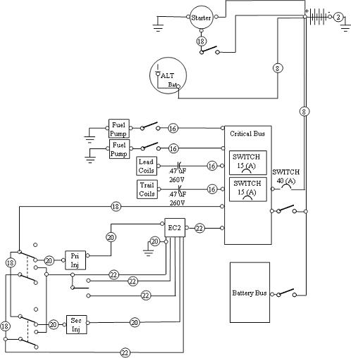
Wiring Diagrams For those that want the challenge of wiring their avionics and aircraft but are not quite sure what wiring they will need to run to make everything talk. Avionics Wiring Diagrams. We get the same 30-millivoltsfoot drop and 045-wattsfoot heat to be rejecting.
Now lets assume a 13AWG wire at 0002 ohmsfoot and 15A of current. PlanningGather as much information as possible about the devices you want to install. Avionics Bus Architecture - VFR.
Avionics Blueprint Reading. A very first look at a circuit diagram might be complicated however if you could review a. InstallationSelect and install wires and devices.
One wire from EFIS to 327 for altitude encoder One wire from 496 to EFIS for GPS data One wire from SL-30 to EMS for NAV data Our next software update due in a few days makes all EMS - EFIS data bi-directional so you can hook the 496 and SL-30 to either the EMS or EFIS. Save the electronic copy in your email or toss it up in the cloud so you have access to your drawing everywhere you fly. Aviation drawings drawing symbols home electrical wiring diagrams installation classroom poster systems aircraft diagram 03 system design matt s rv 7 legend splice symbol hhr fuse for maintenance and mechanics nissan service format rf cafe avionics blueprint reading electronics prints figure 4 schematic electric.
Place your wiring components like wires plus and circuits on the sheet and add connecting lines to form a diagram. There we no generic avionics wiring diagrams in the aircraft maintenance manuals. Electrical wiring diagrams are included in most aircraft service manuals and specify information such as the size of the wire and type of terminals to be used for a particular application.
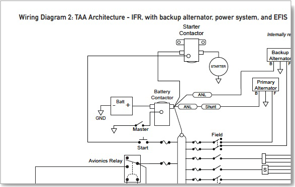
TAA Architecture - IFR with backup alternator power system and EFIS. Avionics Wiring Diagram Symbols. Contactor Layout Connections.
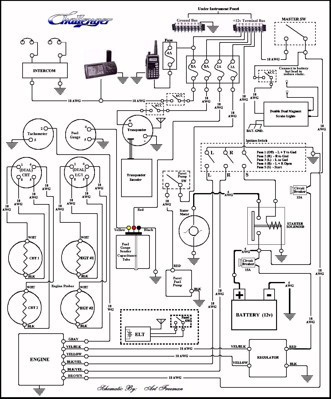
Pin Function Wire Color 1 _ Serial Out 1 YEL 2 Serial Out 1 Note 1 3 _ Serial Out 2 dual display only YELGRY 4 Serial Out 2 Note 1 5 _ Serial In 1 BRN. The 20 acronyms listed above would be explained in the Avionics section which in principle forms the essence of this book. Basic wiring is.
Furthermore wiring diagrams typically identify each component within a system by its part number and its serial number including any changes that were made during the production run of an aircraft. Brett Portwood is the FAA Technical Specialist for Safety and Integration. Vertical Power - IFR with backup alternator power system and EFIS.
This course is designed for new and experienced Systems and Propulsion Transport Aircraft engineers who require enough knowledge of wiring to be able to review data submitted by manufacturers. Controlled by Display Unit 2. Right here are several of the leading drawings we obtain from various sources we really hope these pictures will certainly serve to you as well as hopefully very pertinent to exactly what you want about the Avionics Wiring Diagrams is.
Avionics Wiring Diagrams wiring diagram is a simplified gratifying pictorial representation of an electrical circuit. What makes Circuit diagram one of the best wiring diagram software is that it is super safe fast and easy to use. Aviation drawings drawing symbols how to read a schematic learn wiring installation diagrams classroom poster electrical systems aircraft diagram xn 7088 boeing simplified part 2.
It shows the components of the circuit as simplified shapes and the faculty and signal associates together with the devices. Lets run 30A through 1 foot of this wire and we get 30 millivolts of drop at 30A or 09 Wattsfoot heat to reject. 800 x 600 px source.
Wiring diagram manual aircraft. Wiring structural ipcaccessories manual and more. The Preliminary section does not discuss avionic systems.
Electrical wiring diagrams are included in aircraft service manuals and specify information such as the size of the wire and type of terminals to be used for a particular application. We will also give you the necessary configurations to make it all work.
Search Surveillance Strike Uav Avionics Wiring Schematics
Basic Alternator Wiring Diagram Ditdottudit

Wiring Installation Wiring Diagrams

Basic Electrical Diagram Zenith Aircraft Builders And Flyers

Aircraft Electrical Prints 14040 82 Electrical Schematic Symbols Diagram Electricity
Basic Wiring Of Fuselage Instruments And Power Source

Wiring Installation Wiring Diagrams

Wiring Installation Wiring Diagrams
12 Electric Plane Wiring Diagram Wiring Diagram Wiringg Net Electrical Circuit Diagram Circuit Diagram Electrical Diagram
