Rumbler is an intersection traffic clearing system that interacts with most 100200-watt siren amplifiers to provide secondary low frequency tones. GV2 GV3 and GV7 Manual Motor Starters Controllers and Protectors Catalogue 2013.
Gvan11 Wiring Diagram - If you're looking for video and picture information linked to the keyword you have come to visit the right site. Our website gives you suggestions for seeing the highest quality video and picture content, hunt and locate more enlightening video content and graphics that match your interests. includes one of tens of thousands of video collections from several sources, particularly Youtube, so we recommend this video for you to see. This site is for them to stop by this site.
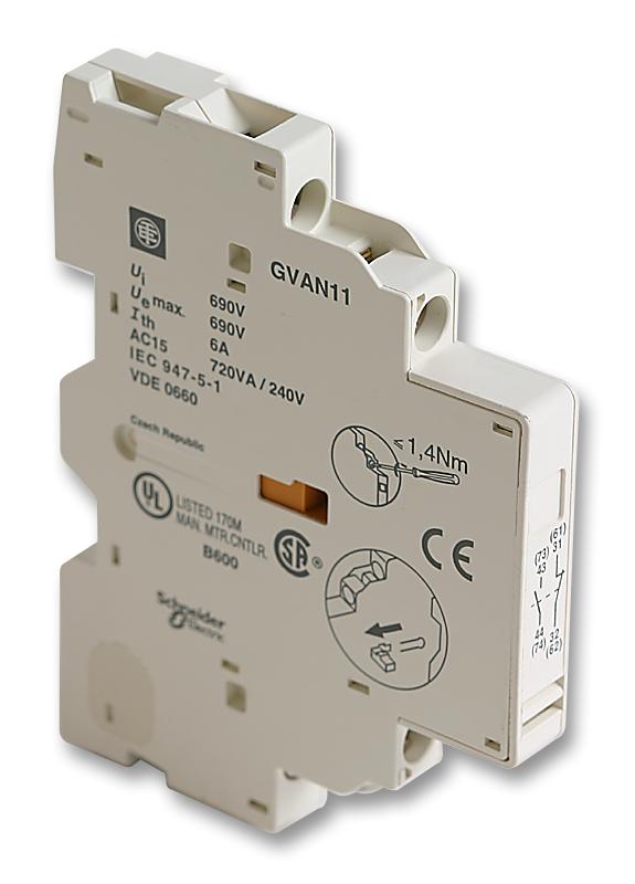
Scheider Electric Gvan11 Auxiliary Contact Block For Schneider Electric Gv2me
Illustration Open Hand Vector.

Gvan11 wiring diagram. Always check the vehicle for proper operation after installation. Telemecanique contactor lc1 d12 10. Model RB-GVAN11 Mounting Kit for the Rumbler.
Our contracting department uses the very best equipment in every electrical installation while proudly holding the NICEIC and SafeContractor accreditations. The Rumbler is particularly. It can be used to create motor starters for any type of application.
Adınız Gönderilecek Kişiler Tavsiye Mesajı İptal Gönder. The Rumbler is a revolutionary new concept to audible warning. Vehicle wiring diagram which is available from the vehicle manufacturer.
Wiring Requirements Cable Types and Wire Sizes for Removable Screw Terminal Block. The motor circuit breaker reference selected above. TeSys D IEC contactor 18 A 3 P 10 HP at 480 VAC nonreversing low consumption 24 VDC coil.
Telemecanique contactor cad50 g7. One Amerian Flag With Stick Vector. 11 Zinc diecasting 12 Stainless steel 13 Varnished 2.
Cole Hersee 24059 Solenoid Wiring Diagram. TeSys D IEC contactor 18 A 3 P 10 HP at 480 VAC nonreversing 36 VDC coil. Single axis stepper driver controller series.
Assembly and wiring of SIRCOVER AC. Telemecanique contactor cross reference. Low frequency tones have the distinct advantage of penetrating solid materials enabling vehicle operators and nearby pedestrians to FEEL the sound waves.
Switch and accessories Linterrupteur et ses accessoires El interruptor y sus accessorios 125A - 160A - 200A 250A - 315A - 400A 500A - 630A 41995012 26995052 26995053 41995012 26995052 26995053 14001020 14001032 14001020. Crouzet Timer 88 8100 manual crouzet 88 8101 EATON pc star ups SERVICE MANUAL pdf wiring diagram slip ring motor resistance starter wiring diagram STAR DELTA motor sequential starter Eaton MCB moeller circuit breaker nzm10-400n siemens softstarter wiring diagram. Ensure that your installation will not affect vehicle operation and safety functions or circuits.
TeSys D contactor is designed for perfect integration in control systems. Wiring diagram dol starter LC1 D12 wiring diagram GV2 AN11 AD0101 GV2 ME20 gv2 me10 GV2 ME05 wiring 3 phase dol starter with emergency stop AP-385 Text. 2007 Chevy Trailblazer Radio Wiring Diagram.
Rated operational voltage of 690VAC at 25Hz to 400Hz and 300VDC for. AC-1 and AC-3 utilization category. Free Next Day Delivery available.
As a combined electrical contractor and wholesaler we can supply you with all types of electrical components from some of the largest manufacturers. Telemecanique contactor lc1 d8011 spec sheet. Motor koruma yan blok gvan11 schneider gvan11 telemecanique gvan11 price gvan11 datasheet gvan11 dimensions gvan11 wiring diagram gvan11 gvan11 cad gv-an11 Tavsiye Et.
2008 - crouzet 88 8100 Automation Controls. The LC1D25G7 is a TeSys D 3-pole Contactor with 3NO power pole and 1NO-1NC auxiliary contacts. Compare Search Please select at least 2 keywords.
Pink Peaceful Yoga Background. Browse our latest Contactors offers. Auxiliary Contact NoNc by Schneider.
Telemecanique contactor wiring diagram. Dark Background With Face. Montage et câblage des SIRCOVER AC.
DATA AND DIMENSIONAL DRAWINGS 21 Technical data 22 Component dimensions non-illuminated 23 Component dimensions illuminated 24 Drilling diagram 25 Circuit diagram 3. Gvan11 Wiring Diagram. The latest upgraded 5 axis breakout board is specially designed for the CNC single axis 2-phase stepper driver controller such as M542 M542H MA860H 2M542 2M982 DM542A DM860A etc.
Barrington Stage Company Logo. Analog Mixed IO Module 3-channel VoltageCurrent Wiring Diagram 1 Voltagecurrent preactuator. Academiaedu is a platform for academics to share research papers.
Small and rugged steel spindle-shaft 68 5bar sealable reflow version available Drilling diagram View from component side 2 Waterproof WD O-Ring and nut supplied Possible modifications on request special type of shaft length form special torque panel mounting waterproof different number of positions. The - poles of inputs IN0 and IN1 are connected internally. Buy Schneider Electric TeSys D LC1D 3 Pole Contactor - 9 A 24 V dc Coil 3NO 4 kW LC1D09BD.
Cat Toy Transparent Background Png. Telemecanique contactor lc1 d09 10. EN FR ES Montaje y conexión de los SIRCOVER AC.
Installing Auxiliary Contacts To Tesys Gv2 Iec Manual Starters Schneider Electric Support Youtube
Search Results For Gvan11 Schneider Electric Motor Drives Datasheets Mouser
15 Honda Activa Electrical Wiring Diagram Wiring Diagram Wiringg Net Electrical Wiring Diagram Electrical Diagram Engine Diagram
Pin On Wiring Diagram
Gvan11 Schneider Electric Contact Block 1no 1nc 6 A
Pin On Electrical Diagram
Nota Evergreen Asas Elektrik Jom Download Sekarang Home Electrical Wiring Electrical Circuit Diagram Electrical Wiring Diagram
16 Basic Electric Drill Wiring Diagram Wiring Diagram Wiringg Net Electric Drill Drill Wiring Diagram
Pin On Ac Wiring


