The Intelligent Bypass when enabled can transfer the motor across the line when the application requires 60Hz. The Z1000 Bypass is BTL listed view listing.
Yaskawa P1000 Wiring Diagram - If you're searching for video and picture information linked to the key word you've come to visit the right blog. Our site gives you suggestions for viewing the highest quality video and image content, search and locate more enlightening video articles and graphics that match your interests. includes one of tens of thousands of movie collections from several sources, particularly Youtube, so we recommend this movie that you view. It is also possible to bring about supporting this site by sharing videos and graphics that you like on this site on your social media accounts such as Facebook and Instagram or tell your closest friends share your experiences about the simplicity of access to downloads and the information that you get on this site. This site is for them to stop by this site.

Yaskawa V1000 Wiring Diagram
01 to 185 kW.
Yaskawa p1000 wiring diagram. YASKAWA AC Drive P1000 MANUAL NO. Schematic Diagram in PDF DWG and DXF formats. 21 rows Yaskawas P1000 Configured package provides a P1000 drive in a NEMA 1 UL Type 1 or.
Schematic Diagram iQpump1000 Configured Type 3R Wall Mount Cabinets W1 thru W3 Impedance Ready With Option TV DSQ1C3R23 171KB 325KB 309KB Rev Date. The Z1000 Bypass Package is optimized with an Intelligent Bypass and advance BAS interface. Schematic Diagram in PDF and DWG formats 1 page Login Sign Up.
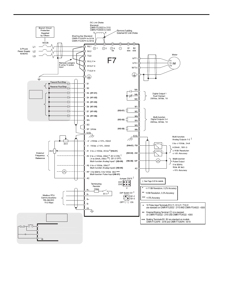
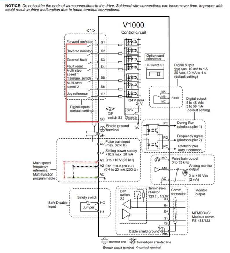
YASKAWA AC Drive - V1000 Compact Vector Control Drive Technical Manual Type. Yaskawas P1000 series AC Drive provides simple reliable cost-effective control for variable torque loads through 1000 HP. Figure 23 Figure 23 RS-485 Terminal Wiring S1 S2 S3 S4 S5 S6 S7 HC SC H1 RP R R9ÙS S9ÙIG P1 P2 PC A1 A2 V AC AM AC MP MA MB MC R R9ÙS S9ÙIG RS-422A or.
And S- to R- as shown in the diagram below. 2-Wire Control Forward Reverse Wiring Diagram. Make sure to follow good wiring practices and all applicable.
The design sets a new benchmark for performance benefits and quality. Yaskawas p1000 configured package provides a p1000 drive in a nema 1 ul type 1 or nema 12 ul type 12 enclosure with space for factory mounted and wired options such as reactors filters circuit breakers fuses network communications and io cards etc. Schematic Diagram for P1000 Configured Type 12 With Option TV 930 and 1200 Amp Models.
12 to 100 HP 480 V. 34 - 1000 HP. 3rd row of terminal board is shown here.
It is beyond the scope of this document to program the V1000 drive for network communication control. Below show the electrical connections for the. 200 V Class Single-Phase Input.
SIEP YAIP1B 01B AC Drive Bypass for Industrial Fans and Pumps Technical Manual Models. How to wire up a Yaskawa V1000 AC Drive presented by Katie Nyberg for Galco TV. P1000 Model Connect Motor and Identification and Mounting Line Power Step 2 tep 3 4 The following procedure is a supplement to other documentation supplied with this equipment and will guide the user in properly wiring the P1000 and motor.
260 YASKAWA ELECTRIC SIEP C710606 10A YASKAWA AC Drive - V1000 PRELIM. Yaskawas P1000 Bypass package provides a P1000 drive in a NEMA 1 UL Type 1 or NEMA 12 UL Type 12 enclosure with space for factory-mounted and wired options such as reactors filters circuit breakers fuses network communications and IO cards etc. 2-Wire Control Forward Reverse S1 S2 S4S3 S5 S6 S7 HC SC H1 RP Wiring Diagram.
3-Wire Control Start Switch Reverse Stop Switch Normally Open Normally Closed Use for momentary contacts Use for maintained contacts NOTE. 34 to 500 HP. Input power and motor terminals for various P1000 models.
Specific application features energy savings and network connectivity make the P1000 a great choice for industrial fans and pumps. Link Start Switch Reverse Stop Switch Normally Open Normally Closed Link V AC A1 A2 A3 FM AM AC RP AC 24V. Please enter at least 3 characters.
01 to 40 kW 200 V Class Three-Phase Input. This robust variable frequency drive is designed from the ground up with application-specific features to maximize energy efficiency. For more product packages see P1000 Configured or P1000.
Buy the items featured in this video at 800-337-1720 or visit. 2-Wire Control Forward Reverse S1 S2 S3 S4 S5 S6 S7 HC SC H1 RP Wiring Diagram. Select the proper diagram for the model you are installing.
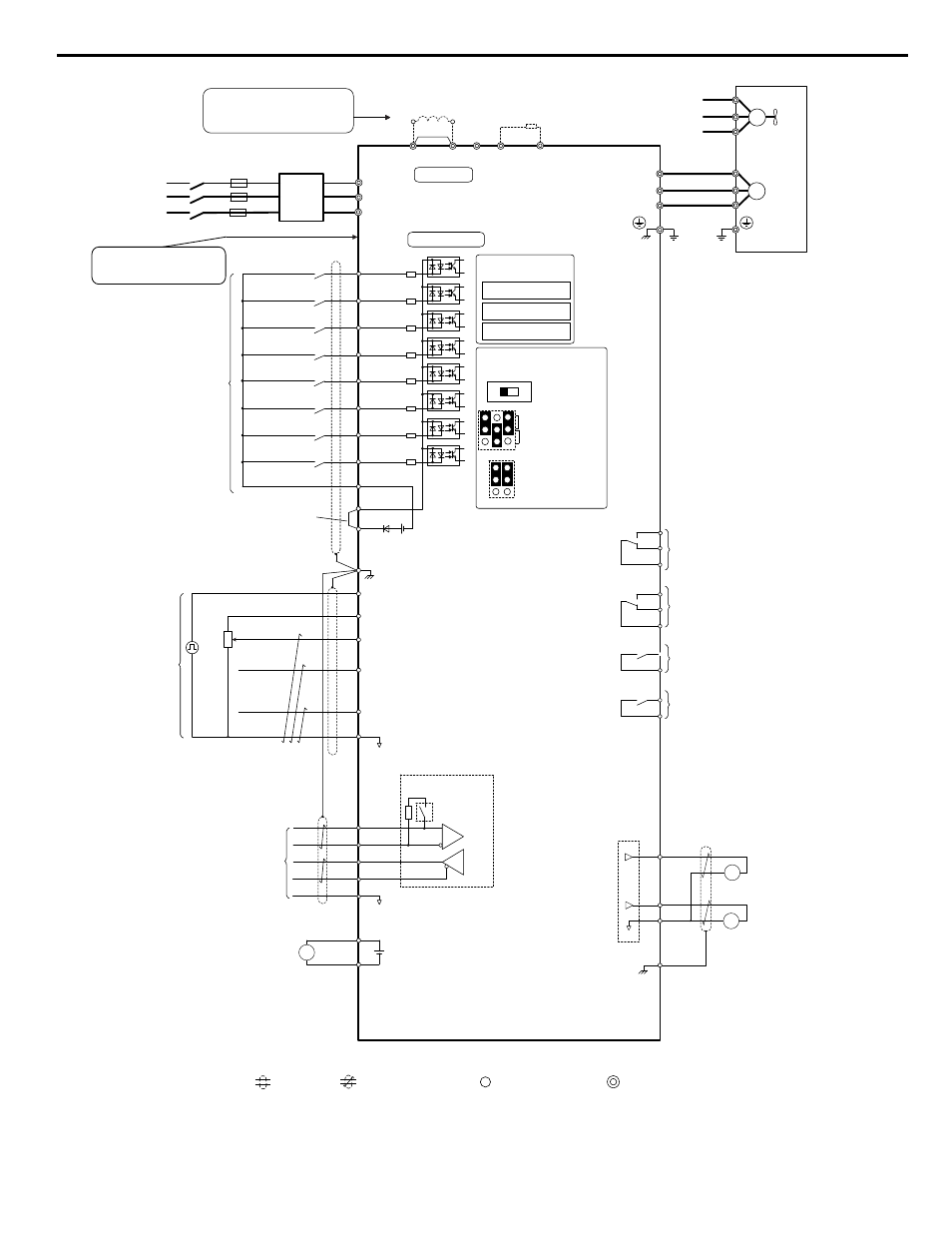
P1000 Drive Elementary Schematic. Standard connection diagram for control and main circuit wiring for j1000 drive. It will also show the user how to configure the P1000 for a general purpose application.
Schematic Diagram in Word PDF and DWG formats 1 page For Base Models. 3-Wire Control Start Switch Reverse Stop Switch Normally Open Normally Closed Use for momentary contacts Use for maintained contacts NOTE. It is beyond the scope of this document to program the V1000 drive for network communication control.
The P1000 drive provides simple reliable cost-effective control for variable-torque loads through 1000 HP. P1B2D343 P1B2D396 P1B2B240 - P1B2B590 Option PA Dual Motor AND. 3-Wire Control U sef orm n tay c Use for maintained contacts User Terminals User Terminals Set Parameter A1-03 to 3330 Note.

Yaskawa P1000 Technical Manual Pdf Download Manualslib
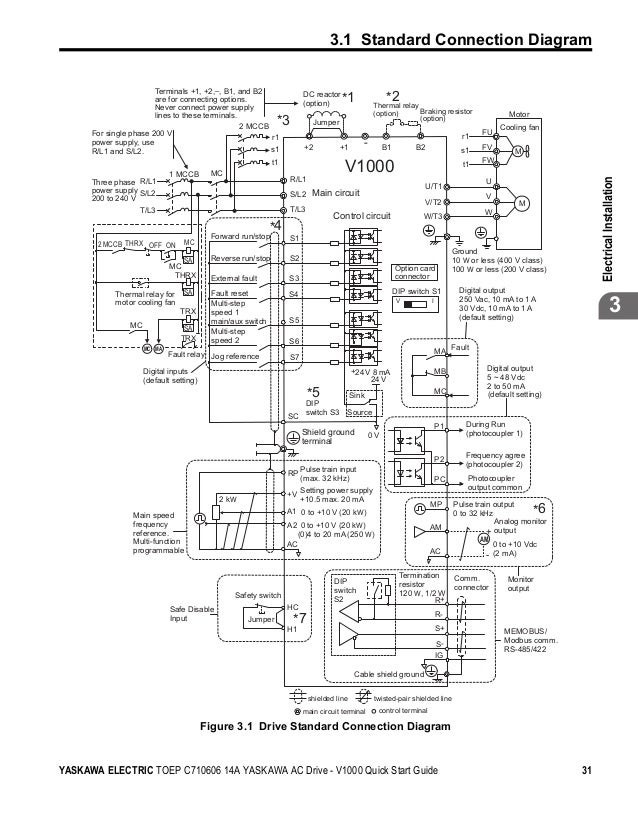
Yaskawa V1000 Wiring Diagram

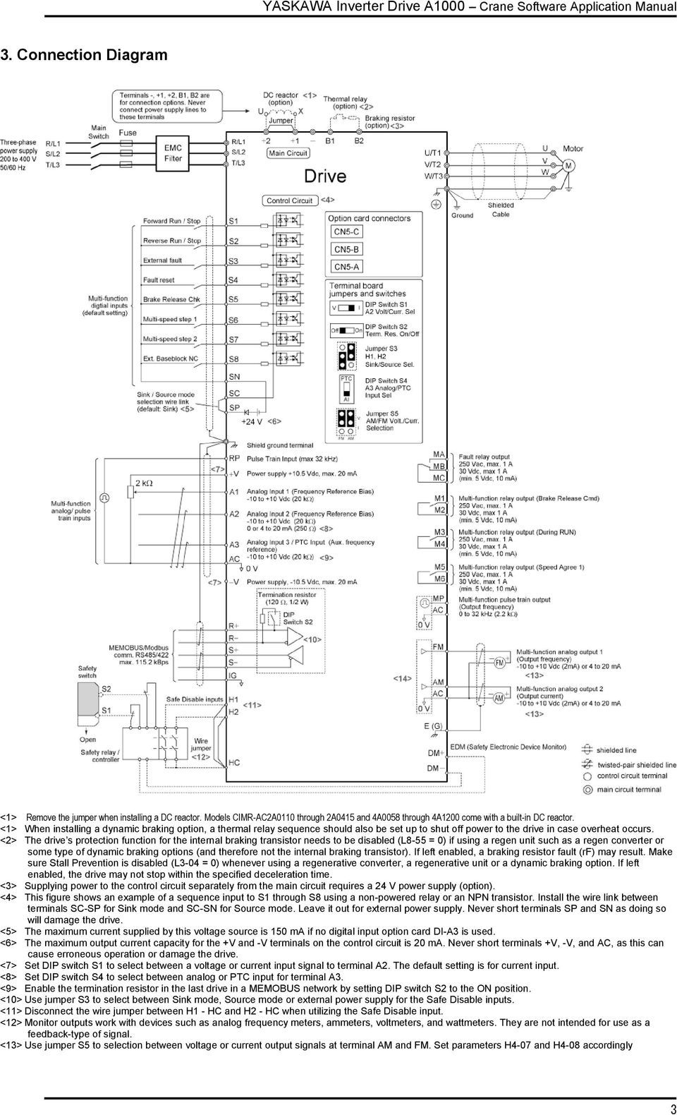
Yasakawa Yaskawa A1000 Ac Drive 1 Hp To 650 Hp 1 3 Phase For Motor Speed Controlling Id 19161941097
Yaskawa A1000 Installation Manual
Yaskawa A1000 Drive Manual

Yaskawa V1000 Wirihg Connection Yaskawa Potentiometer Connection Yaskawa Wiring Diagram V1000 Youtube
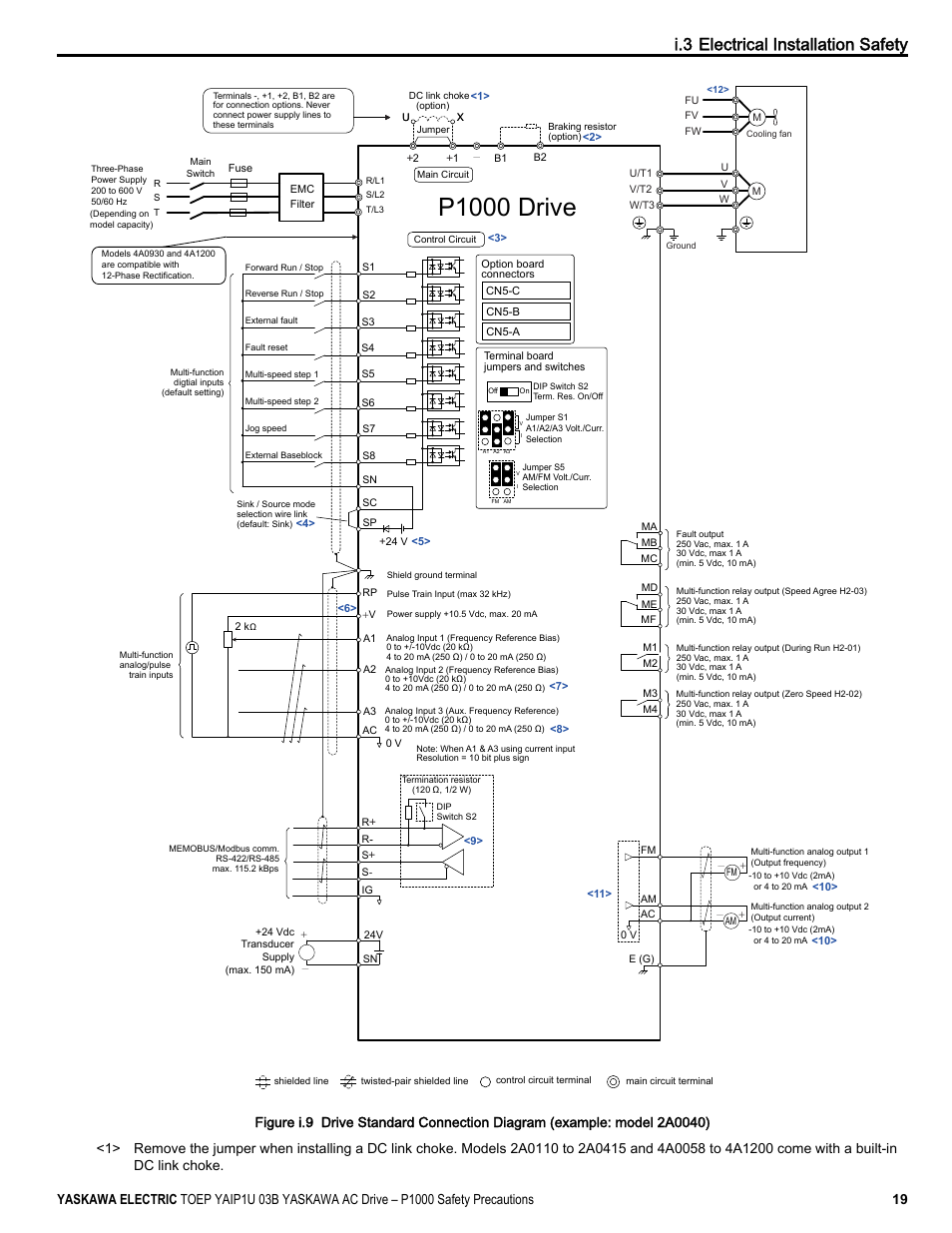
P1000 Drive I 3 Electrical Installation Safety Yaskawa Cimr Pu User Manual Page 19 74
P1000 Drive I 3 Electrical Installation Safety Yaskawa Cimr Pu User Manual Page 19 74
Yaskawa V1000 Wiring Diagram
