10b2f Honeywell Thermostat Wiring Color Diagram Digital Resources. 2 on page 3.
Honeywell Spyder Wiring Diagram - If you're searching for video and picture information related to the keyword you have come to visit the right site. Our site provides you with hints for seeing the highest quality video and picture content, search and locate more enlightening video articles and graphics that fit your interests. comprises one of thousands of video collections from several sources, particularly Youtube, so we recommend this video for you to see. It is also possible to bring about supporting this site by sharing videos and images that you enjoy on this blog on your social media accounts like Facebook and Instagram or tell your closest friends share your experiences about the ease of access to downloads and the information that you get on this website. This blog is for them to visit this site.
Wlkfwm Wireless Receiver User Manual 62 0291 D Fm Honeywell
Page of 24 Go.

Honeywell spyder wiring diagram. The Spyder BACnet controller provides a SHLD terminal which is electrically isolated. 10 to 13 mm square or round VAV box damper shaft. Mm connects to a terminal block in the subbase.
45F to 99F 7C to 37C. The actuator mounts directly onto the VAV box damper shaft and has up to 44 lb-in. If resistance exceeds 550 Ohms voltages up to 18 Vdc are possible at the analog output terminal.
Page of 24 Go. Field wiring 16 to 22 AWG 131-033 sq. SPYDER BACNET PROGRAMMABLE CONTROLLERS.
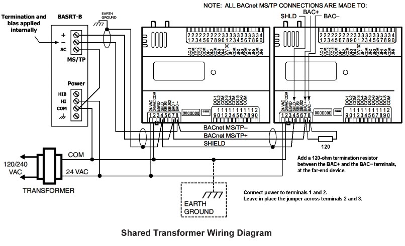
This will be called the near-end. The Spyder controllers utilize a two-wire non-isolated MSTP network while the BASrouter supports a 3-wire isolated MSTP network. The Zio TR70 Series TR70 TR70-H TR71 TR71-H TR75 and TR75-H OS numbers LCD Wall Modules provide an operator interface for monitoring and adjusting parameters in the wall module itself and in the programmable controller refer to the Honeywell Spyder Users Guide form 63-2662 or the ComfortPoint Programmable Controller Users Guide form 63-2663 depending on the programmable controller used to which it is wired.
The relay outputs are internally designed to provide up to 3 isolated banks of contacts. Spyder with Relays OS numbers WIRING The digital outputs of the Spyder with relay are designed differently and therefore are wired differently than the other Spyder products. SPYDER BACNET PROGRAMMABLE CONTROLLERS 63-132808 2 DESCRIPTION The programmable VAVUnitary controllers are available in three models as described in Table 1.
All modules can be mounted on a standard two by four inch junction box or on a 60 mm diameter junction box. Follow Honeywell cabling and grounding recommendations. We are the leading suppliers of domestic heating and combustion controls in the UK with products that include time temperature gas and water controls.
A One Universal Input UI-1 is user selectable as a fast digital pulse meter Each controller is programmable because the user chooses which function blocks to use and how to connect them. If possible install the BASrouter at one end of the MSTP segment. WARNING Electrical Shock Hazard.
The Honeywell Spyder Tool can be used to program the Spyder controller in the following two ways. 5 Nm torque 90-degree stroke and 90 second timing at 60 Hz. The actuator is suitable for mounting onto a 38 to 12 in.
Since many non Honeywell devices do not have such a terminal it is important for the installer to still connect the. Mechanism which is shipped hard-wired to the controller. Our Wiring Diagrams section details a selection of key wiring diagrams focused around typical Sundial S and Y Plans.
Honeywell Thermostat Rth3100c Wiring Diagram Usb 5v Power Supply Schematic Hondaa Accordd Bmw1992 Warmi Fr Honeywell rth3100c installation issues thermostat wiring compatibility rth111 diagram doityourself 480v full gio atv install model rth111b quotes for manual rth3100c1002 colemen 7 wire likewise rth6580wf guide th3210d1004 to just installed modutrol. 70ae0 Honeywell Thermostat Rth6500wf Wiring Diagrams Digital. SPYDER BACNET PROGRAMMABLE CONTROLLERS.
The Honeywell Spyder Tool provides the programming environment for the Honeywell Spyder controllers. Honeywell PUB6438S User Manual. Honeywell Aquastat Wiring Diagram Eyelash Me.
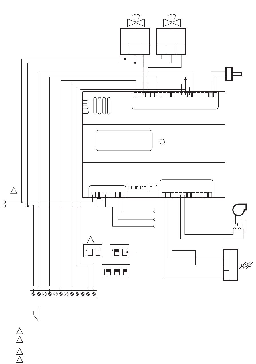
Controller wiring diagram model PUB6438S shown for typical AHU application. Follow Honeywell cabling and grounding recommendations. Communication Wiring The Spyder controllers utilize a two-wire non-isolated MSTP network while the BASrouter supports a 3-wire isolated MSTP network.
PUB4024S - Programmable BACnet Micro Spyder Controller. If possible install the BASrouter at one end of the MSTP segment. Thermostat Wiring Diagrams Wire Installation Simple Guide.
49ff3 Honeywell Smart Valve Wiring Diagram Digital Resources. Diagram Honeywell Boiler Control Wiring Diagrams Full Version Hd. 6 Wire Honeywell Thermostat Wiring Diagram.
Disconnect power supply before beginning wiring or making wiring connections to prevent electrical shock or equipment damage. Honeywell Smart Thermostat Wiring Instructions Rth9580wf Tom S. Our product range is designed to provide the homeowner with the best in comfort energy and health solutions.
Install The Honeywell Wi Fi Smart Thermostat In A Snap Cnet. Controller wiring diagram model PUB6438S. Wiring Diagrams Contains all the essential Wiring Diagrams.
This will be called the near-end. INSTALLATION The device must be mounted in a position that allows clearance for wiring servicing and removal. Honeywell PUB6438S User Manual.
The factory installs removable jumpers between 24VAC and common of. It is developed with using Niagara AX framework developed by Tridium and runs in the Niagara Runtime environment. Please request a quote and a member of our team will contact you for pricing and availability.
SPYDER LON PROGRAMMABLE VAVUNITARY CONTROLLERS 63-268505 4 Hardware driven by the analog current outputs must have a maximum resistance of 550 Ohms resulting in a maximum voltage of 11 volts when driven at 20 mA. This terminal is a convenient way to connect the shield of the two MSTP cable segments comprising the daisy chained bus see Figure 2. Visio Honeywell Diagram 240v 1000 Or 2000 Watts New Vsd.
Item Restricted to Honeywell Contractors. Devices UI Universal Input DI Digital Input AO Analog Output DO Digital Output.
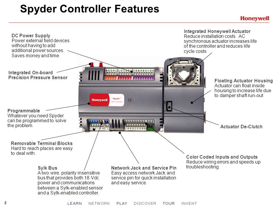
Spyder Introduction Ppt Video Online Download

Page 14 Of Honeywell Universal Remote Pub4024s User Guide Manualsonline Com
Https M Products Ecc Emea Honeywell Com Australia Pdf En 63 2685 As01r0314 Pdf
Https Www Emon Com Literature Spyder Model 5 Compact Vav Controller Installation Instructions 31 00362 Pdf

Honeywell St9120c4057 Wiring Diagram Download Wiring Proposal Surat Tulisan
Wlkfwm Wireless Receiver User Manual 62 0291 D Fm Honeywell
Page 18 Of Honeywell Universal Remote Pub6438s User Guide Manualsonline Com

63 2689 07 Spyder Bacnet Programmable Controllers
Automatedbuildings Com Article Using The Basrouter With A Honeywell Spyder Controller
