1 re-used short interior screw anchors one side of the gearmotor on the other side 1 m3x20 secures the case to the mount. Nerf Guns or Nerf Blasters are toy dart gun products owned by Hasbro that fire ammunition such as darts discs or balls constructed from foam.
Nerf Stryfe Wiring Diagram - If you're looking for video and picture information related to the key word you've come to pay a visit to the ideal blog. Our site gives you hints for viewing the highest quality video and image content, hunt and find more enlightening video content and graphics that fit your interests. comprises one of tens of thousands of video collections from several sources, especially Youtube, so we recommend this movie for you to see. You can also bring about supporting this site by sharing videos and graphics that you enjoy on this site on your social media accounts such as Facebook and Instagram or tell your closest friends share your experiences concerning the simplicity of access to downloads and the information you get on this site. This blog is for them to stop by this site.
Stryfe Flywheel Braking Modifications Nerfhaven
Definitive elite stryfe step by step tutorial duration.

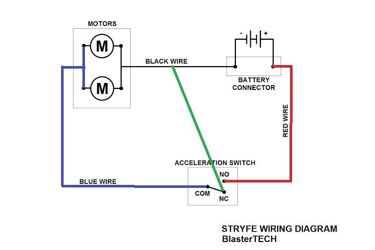
Nerf stryfe wiring diagram. Our traditional mechanical micro-switch wiring kit for the Stryfe. I get my LEDs from Bright Components on eBay. Nerf Stryfe Re-Wire Part 1 - YouTube.
This is a good entry level modification for the novice modder wiring diagram for electric braking on a stryfe. With the simplest of circuits. This is a good entry level modification for the novice.
That wiring is exactly correct. Copy my wiring if you dont know what youre doing. Launched in 2003 the products in the Nerf N-Strike series are among the most notable Nerf.
It covers a full tear down followed by re-wire using the stock rev switch and motors. Ive mainly seen the use of high-amperage micro-switches in this community but as tech in blasters microcontrollers brushless motors continues to expand and the motor-arms-race delivering new high-draw motors to the scene its time for another MOSFET guide without confusing the. I use a 280 ohm resistor for Nerf builds wire the LED to the jam door switch so opening the door turns it off or on according to preference.
Your first nerf stryfe mod guide. For the jam door volt meter just hook the wires to the NC side of the stock jam door lock switch. Keep in mind this photo shows the wiring for the DIY Firefly tech lighting as well.
Regards the Rapdistrike Id also advise nuking the internal wiring and rewiring according to this diagram Use some 18AWG hobby teflon coated hobby wire eBay or your local hardware store ought to have some. Connecting rod 2 3mmx6mmx25mm bearings 2 m3X6mm button head screws and 2 m3 washers. I have almost that exact setup in my Stryfe.
You want stranded never solid. Red is positive green is negative. I was out of black wiring.
Firstly there are 2 classes of insulated copper electrical wire. If playback doesnt begin shortly try restarting your device. Ben meaning to make an afterburner system for awhile me thinks you haveJul 04 Help please.
It has absolutely no place in a gun where it has to be snaked through tight spaces flexed and subjected to. Also I added an extra switch for the Stryfe under the carry handle to prevent myself from bumping my motor rev switch when Im not playing. I dont think youll save much in the way of battery life leaving the stock wiring theres probably a net loss because of the resistance of the thin stock wire - citation needed.
Stryfe Circuit Diagram LiPo low voltage alarm. Working on creating videos explaining the wiring of various electronic blasters. Mar 31 wiring diagram.
Stage 1 Click here for circuit diagram. 1x JST Female plug pre-wired 4 ¾. I Made a Handy Nerf Infinus Circuit Diagram.
Stryfe Circuit Diagram LiPo low voltage alarm. Posted Image wire up your blaster using the high quality wire and solder check all the clearances and close up the blaster. Low Voltage Alarm Recommended battery pack 3S LiPo.
Solid wire is used for stationary applications like mains wiring in buildings. As for where to put the motor braking toggle switch I dont know what to tell you. I did a video on LEDs and Voltmeters too.
Starting with the Stryfe and all its variants I hope it helpsEmail Add. Everything else is replaced leaving a wonderfully simple 3 wire set up. Diy wiring switch kit stryfe stryfe release the potential of you blaster.
There havent been too many so Ill add mine to the list. Testing performed in a controlled scenario with brand new Elite darts Click here for installation instructions. Thank you so much for watching.
Its time for an easy MOSFET wiring guide. Stock wires will work fine for that since the volt meter pulls very little current. Press the bearing into the connecting rod Im.
Nerf Stryfe Re-Wire Part 1. The first Nerf Blaster the Nerf Blast-A-Ball was released in 1989. Some of you were keen for an idiots guide to wiring the Stryfe as a certified idiot I produced this two part epic.
DIY Wiring Switch Kit - Stryfe Stryfe Release the potential of you blaster. Stryfe Installation Guide Stage 1 Click here for circuit diagram. Put the voltmeter on a separate feed before the LEDs I place them on the flat panel under the jam door in Stryfe.
Installation of a Turnigy Lipo beneath the jam door hatch which will provide power 84v in place of the stock AAs thus leaving the AA battery tray empty and unmodified preserving its use for times when lower power is preferred. 3S LiPo Battery Pack Use with Battery Tray Expander sold separately Recommended battery pack 2S LiPo.

Overvolting Stryfe And Rapidstrike Nerf
Stryfe Mod Planning Wiring Help Nerf
Stryfe Full Auto Kit From Monkee Mods Circuit Diagram Nerf

Stryfe Full Auto Kit From Monkee Mods Circuit Diagram Nerf

Outback Nerf Mod Fk 180ph 3250 Rapidstrike Pusher Motor


Circuit Question Swapping Between Power Supply Modifications Nerfhaven
My Plan For Stryfe Wiring For Door Activated Voltmeter And Toggleable Motor Braking Plus A Few Questions Nerf
