Refer to the publications listed in Additional Resources on page 10. Install and ground a 1756 chassis and power supply.
1756 If4fxof2f Wiring Diagram - If you're looking for video and picture information related to the key word you've come to visit the ideal site. Our website provides you with hints for seeing the highest quality video and image content, hunt and locate more informative video articles and images that fit your interests. comprises one of thousands of movie collections from several sources, especially Youtube, therefore we recommend this movie for you to view. You can also contribute to supporting this website by sharing videos and images that you like on this site on your social networking accounts like Facebook and Instagram or educate your closest friends share your experiences about the ease of access to downloads and the information that you get on this website. This site is for them to stop by this website.

Ab Allen Bradley Compactlogix Plc 1769 If4 Buy Allen Bradley Micrologix Plc Allen Bradley Modul Allen Bradley 1756 Plc Product On Alibaba Com
Professional 1756 Ib32 Allen Bradley Controllogix Digital I O Modules B Supplier Manufacturer Amikonltd Com.
1756 if4fxof2f wiring diagram. The ControlLogix architecture uses ProducerConsumer technology which allows input information and output status to be. 1756 if6i wiring diagram - Wiring Diagram The 1756-IF6I module changes analog signals into digital form for inputs and convert the digital form to analog signals for outputs. When the module runs beyond its limits set by the input range the under-rangeover-range detection.
View online or download Allen-bradley ControlLogix 1756-IF4FXOF2F Installation Instructions Manual. Upper and lower tongue-and-groove slots guide the module during installation and secure the module within the system. 1756 ControlLogix IO Specifications 1756 Series Catalog Numbers The ControlLogix architecture provides a wide range of input and output modules to span many applications from high-speed digital to process control.
Order and receive an RTB or IFM and its components for your application. 1756 ControlLogix IO Specifications The ControlLogix architecture provides a wide range of input and output modules to span many applications from high-speed digital to process control. 1492-IFM40F 1492-AIFM8-3 1492-IFM20F 1492-AIFM6S-3 1492-AIFM8-3 WIRING 1492-AIFM16-F-3 1492-IFM40F-FS120-2 wiring diagram 1492-ACABLE 1492.
Before you install and use your module do the following. Interface Module 1756-UM051 User Manual 1756-IF4FXOF2F ControlLogix High Speed Analog IO Module Original. Chassis 1756-A4 1756-A7 1756-A10 1756-A13 1756-A17 Chassis compatibility Series A Series B Series B Wire size 25 mm2 14 AWG solid or stranded copper wire rated at 90 C 194 F or greater 12 mm 364 in insulation max Wire category 1 - on power ports5.
1756-IF4FXOF2F Current Mode Wiring Diagram - i IN-1V IN-0V 2-Wire IN-1I. 2009 - 1492-IFM40F wiring diagram. Module block diagrams and inputoutput circuit diagrams Chapter 5 Full description of ControlLogix Sourcing Current Loop Input Module 1756-IF6CIS Chapter 6 Full description of ControlLogix Thermocouple Input Module 1756-IT6I2 Wire Off Detection with the 1756-IR6I module Appendix A Specifications for 1756-IF6CIS module.
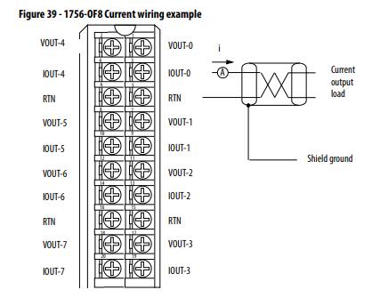
Plc Hardware Allen Bradley 1756 If8 Series A In Plch Packaging. Once the modules are locked together the system becomes a rugged assembly. The example below shows how to wire the module.
The controllers can use these signals for various control purposes. 1756-OF8H motor operated valve 1756-TBNH 1756-IF8H 8 channels wiring diagram 1756-IN608 apparatebau hundsbach 1756-OF8 1794-ACNR 1492-AIFM8-3 Text. Wiring System Type Description Terminals Per Channel Fixed or Removable Terminals Wiring System IFM Module Catalog Number Screw RTB required Pushin RTB required Cable Cat.
Rockwell Automation Publication 1756-TD002J-EN-P - November 2016 219 1756 ControlLogix IO Specifications Switching frequency max 1 operation3 s 03 Hz at rated load Bounce time mean 12 ms Expected contact life 300 kHz resistive 100 kHz inductive Scheduled outputs Synchronization within 167 s max reference to the Coordinated System Time. PLC Card Wiring System 7SH M Description Terminals Per Channel Fixed or Removable 7HUPLQDOV Wiring System IFM Module Catalog Number Screw RTB required Push-in RTB required Cable Cat. RTBs and IFMs are not included with the IO modules.
They must be ordered separately. Vh 1754 Plc Wiring Diagrams Also Allen Bradley 1756 On Card Free Diagram. See 1756 Removable Terminal Blocks on page271 and Wiring Systems on page272.
Removable terminal blocks help ease the wiring task. NoWiring Diagram 1756HSC 1224V DC High Speed Counter Encoder 2 Channel 1 F 1492AIFMCE4 1492ACABLEXA41170 723 Fusible High Speed Counter Encoder 2 Channel. IO wiring can be routed from beneath the module to the IO terminals.
1756-TD002A-EN-E 1756-PA75 1756-IF8 8 channels wiring diagram 1756-IF8H 1756-TBNH 1756-OB16D 1756-PA72c 1756-IF4FXOF2F Allen-Bradley 1756-OF8 1756-TBCH 1756-OW16I. Updated diagram labels for wiring the 1756 if6i module chapter 6 updated fahrenheit temperature conversion range values for cold junction compensation types and cold junction offset option added advisory not to exceed the spec ific isolation voltage when using a separate power source when wiring various modules. Rockwell Automation Publication 1756-UM005B-EN-P - January 2013.
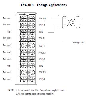
Wiring Diagrams Figure 5 Voltage And Cur Inputs Rockwell Automation 1756 Of8h Controllogix Hart Analog I O Modules User Manual Page 60 228 Bulletin 1492 I O Wiring Conversion Systems Selection Guide Wiring Controllogix Digital Input. 1756 If6i Wiring Diagram. To connect all field-side wiring.
Wiring Diagram 1756-OF4 Voltage 4 Channel Input Output or 2 Input 2 Output 3 F 1492-AIFM4-3 ³ ³ 1492-ACABLEVA 41170-493. Allen-bradley ControlLogix 1756-IF4FXOF2F Pdf User Manuals. Standard IO Module Wiring 1756 ControlLogix standard IO modules require either a Removable Terminal Block RTB or a 1492 interface module IFM to connect all field-side wiring.
Figure 12 - 1756-IF4FXOF2F Current Mode Wiring Diagram. ControlLogix High Speed Analog IO Module 11 Wire the Module You can only connect wiring to your module through an RTB or IFM. Xl 6369 1769 If8 Wiring Schematic.
The ControlLogix architecture uses Producer-Consumer technology which allows input information and output status to be shared.
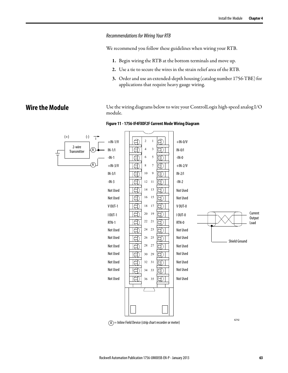
Wire The Module Recommendations For Wiring Your Rtb Rockwell Automation 1756 If4fxof2f Controllogix High Speed Analog I O Module User Manual Page 63 152
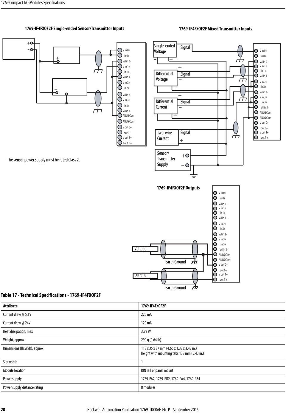
1769 Compact I O Modules Specifications Pdf Free Download
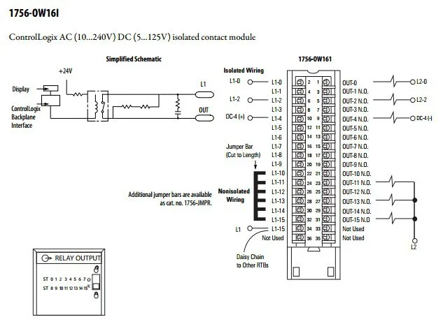
Allen Bradley Plc Pemrograman 1756 Ow16i 16 N O Output Terisolasi Terpisah Dengan Harga Terbaik Buy Ac Dc Terisolasi Hubungi Modul Analog Output Modul Plc Pengukur Amper Dengan Output Product On Alibaba Com

1769 Compact I O Modules Specifications Pdf Free Download

Rockwell Automation 1756 If4fxof2f Controllogix High Speed Analog I O Module User Manual Page 64 152
Allen Bradley 1756 Of8 1756 Of4 1756 Of4k 1756 Of8i 1756 Output Module Oleh Pt Total Abadi Solusindo Authorized Distributor General Contractor Di Jakarta Timur
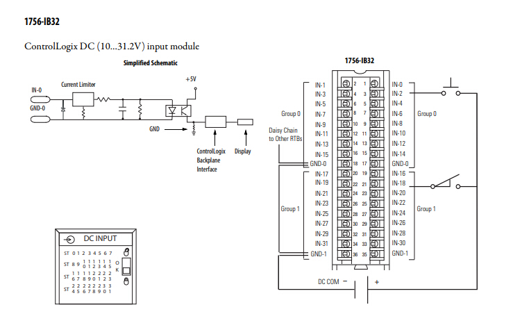
Professional 1756 Ib32 Allen Bradley Controllogix Digital I O Modules 1756 Ib32 B Supplier 1756 Ib32 Allen Bradley Controllogix Digital I O Modules 1756 Ib32 B Manufacturer Amikonltd Com
Allen Bradley 1756 Of8 1756 Of4 1756 Of4k 1756 Of8i 1756 Output Module Oleh Pt Total Abadi Solusindo Authorized Distributor General Contractor Di Jakarta Timur
Https Cours Etsmtl Ca Gpa754 References Fabricants Logix Complement High Speed Pdf
