Individually isolated 2 pointsgroup. It does not satisfy the requirements for general IO fault tolerance.
1756 Ox8i Wiring Diagram - If you're looking for video and picture information related to the keyword you've come to visit the right blog. Our site gives you suggestions for seeing the highest quality video and picture content, search and find more enlightening video content and graphics that match your interests. includes one of thousands of video collections from various sources, particularly Youtube, so we recommend this video for you to view. You can also bring about supporting this site by sharing videos and images that you like on this site on your social networking accounts such as Facebook and Instagram or tell your closest friends share your experiences concerning the ease of access to downloads and the information you get on this site. This site is for them to stop by this website.

Professional 1756 Ig16 Ab In Stock Ready For Ship Supplier 1756 Ig16 Ab In Stock Ready For Ship Manufacturer Amikonltd Com
Due to the magnitude of current through the LED the 1756-0B16D PLC module No Load diagnostic function will not work.
1756 ox8i wiring diagram. Individually isolated two points per group Pilot duty C300R150. You must order separately. 1756 Tbnh Wiring Diagram wiring diagram is a simplified welcome pictorial representation of an electrical circuit.
2010 - Allen-Bradley 1756-L61 MTBF. Per IO Description Fixed Terminal Block Removable Terminal Block RTB Plugs Bulletin 1756 ControlLogix IO Module 1756-IA16I 1756-IB16D 1756-IB16I 1756-IA32 1756-IB32 1756-IV32 1756-IH16I 1756-IM16I 1756-OA16I 1756-OB8EI 1756-OB16D 1756-OB16I 1756-OB16IS 1756-OB32 1756-OV32E 1756-OH8I 1756-OW16I 1756-OX8I Cat. 2A 5-30V DC 05A 48V DC 025A 125V DC 2A 125240V AC.
Allen-Bradley 1756-OX8I Outputs. 218 Rockwell Automation Publication 1756-TD002J-EN-P - November 2016 1756 ControlLogix IO Specifications 1756-OX8I ControlLogix AC 10240V DC 5125V isolated contact module Technical Specifications - 1756-OX8I Attribute 1756-OX8I Outputs 8 NO. 31W 60C 140F.
Current draw 24V. 1756 ControlLogix Removable Terminal Blocks RTBs Provides a flexible interconnection between plant wiring and IO modules. Current draw 51V.
Allen-Bradley Rockwell Automation. ControlLogix Chassis Installation Instructions 1756-IN080 1756-PA72B -PB72B ControlLogix Power Supply Installation Instructions 1756-567 1756-PA75 -PB75 ControlLogix Power Supply Installation Instructions 1756-578 1756-Series ControlLogix Module Installation Instructions Each module has separate installation document Multiple 1756-IN numbers. See 1756 Removable Terminal Blocks on page271 and Wiring Systems on page272.
Allen-Bradley 1756-OX8I ControlLogix 8-Ch ACDC Isolated Relay Output Module. 178 Appendix A Troubleshoot Your Module Status Indicators forInputModules. Safety IO Module Wiring 1756-IB16S 1756 ControlLogix 16-point Sinking Safety Input Module has been agency certified using only the ControlLogix RTBs 1756-TBCHS or 1756-TBS6HS.
93 Drive Different Loads with the 1756-OF8I Module. 14 This 1492 module is for use in SIL2 safety systems only. Rockwell Automation Publication 1756-TD002I-EN-E - June 2015 3 1756 ControlLogix IO Specifications 1756-IA8D ControlLogix 120V AC diagnostic input module Table 1 - Diagnostic Specifications - 1756-IA8D Attribute 1756-IA8D Open wire Off-state leakage current 15 mA min Loss of power Transition range 4685V AC Timestamp of diagnostics 1 ms.
10-265V AC 47-63Hz. If this function is required use the Cat. 239 Appendix A Troubleshoot Your Module Introduction.
Not shipped with IO modules. 213 Rockwell Automation Publication 1756-UM533E-EN-P - November 2016 9. Wire the 1756-IF8 Module.
To use this module in a SIL2. 1756-IF16 1756-UM009B-EN-P 1756-IF8 8 channels wiring diagram 1756-OF8 1756-IF8 1492-AIFM8-3 WIRING 1756-OF4 1756-IR6I 1492-AIFM8-3 1756-OF4 WIRING DIAGRAM 1756-IF6I. 211 Reconfigure a Module.
Unlatch Alarms in the 1756-OF8H or 1756-OF8IH Module. Wiring Diagrams 1756-IA8D. Per IO Description Fixed Terminal Block Removable Terminal Block RTB Plugs Bulletin 1756 ControlLogix IO Module 1756-IA16I 1756-IB16D 1756-IB16I 1756-IA32 1756-IB32 1756-IV32 1756-IH16I 1756-IM16I 1756-OA16I 1756-OB8EI 1756-OB16D 1756-OB16I 1756-OB16IS 1756-OB32 1756-OV32E 1756-OH8I 1756-OW16I 1756-OX8I Cat.
65 1756-IF16 Module Fault and Status Reporting. RTBs are not included with the IO modules. 96 Fault and StatusReporting.
Allen-Bradley 1756-OX8I IO Module Contact Output 8 Channel 125VDC 125240VAC. It shows the components of the circuit as simplified shapes and the power and signal connections along with the devices. Includes screw-clamp or spring-clamp terminations.
They must be ordered separately. 1756 HART Analog Isolated IO Modules.
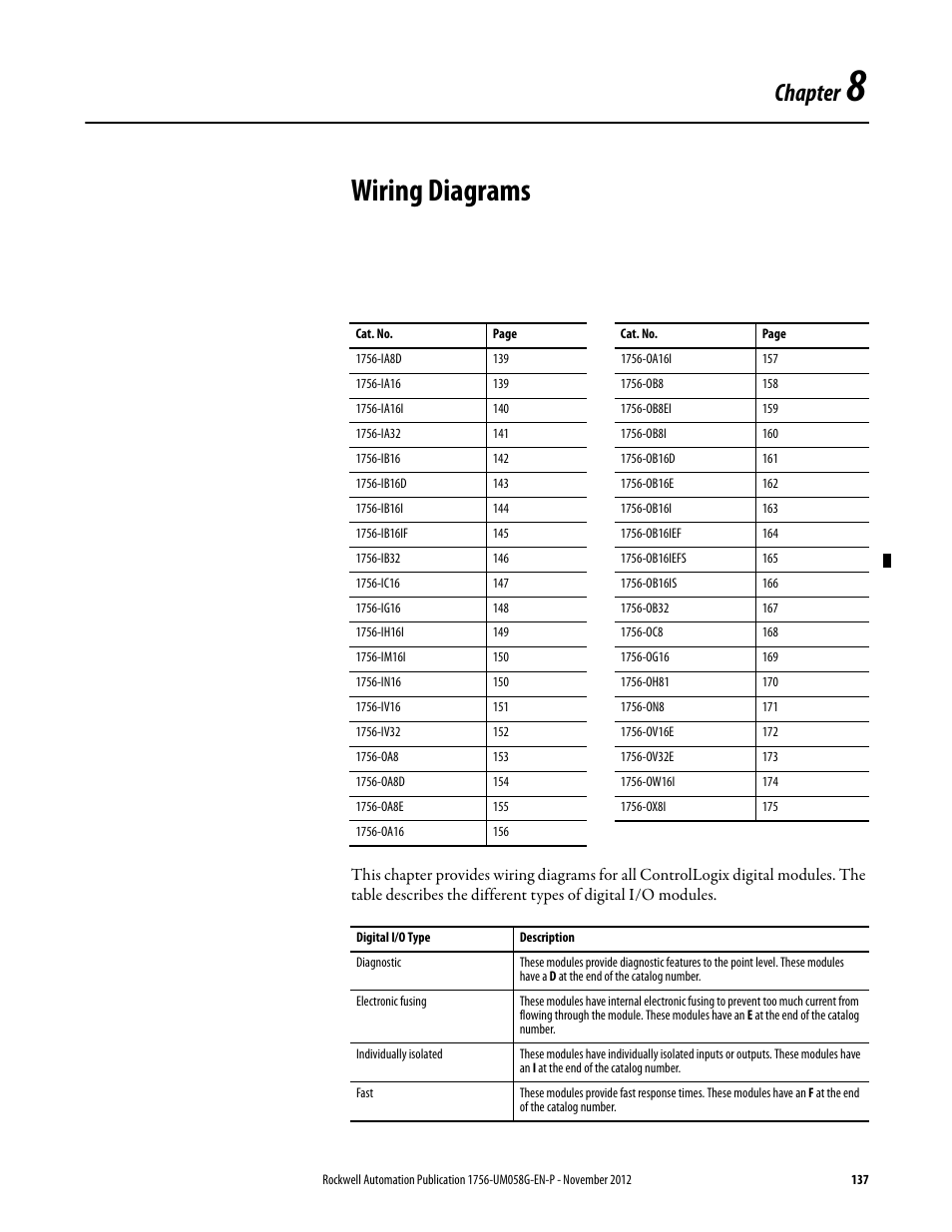
8 Wiring Diagrams Chapter 8 Wiring Diagrams Rockwell Automation 1756 Xxxx Controllogix Digital I O Modules User Manual Page 137 258
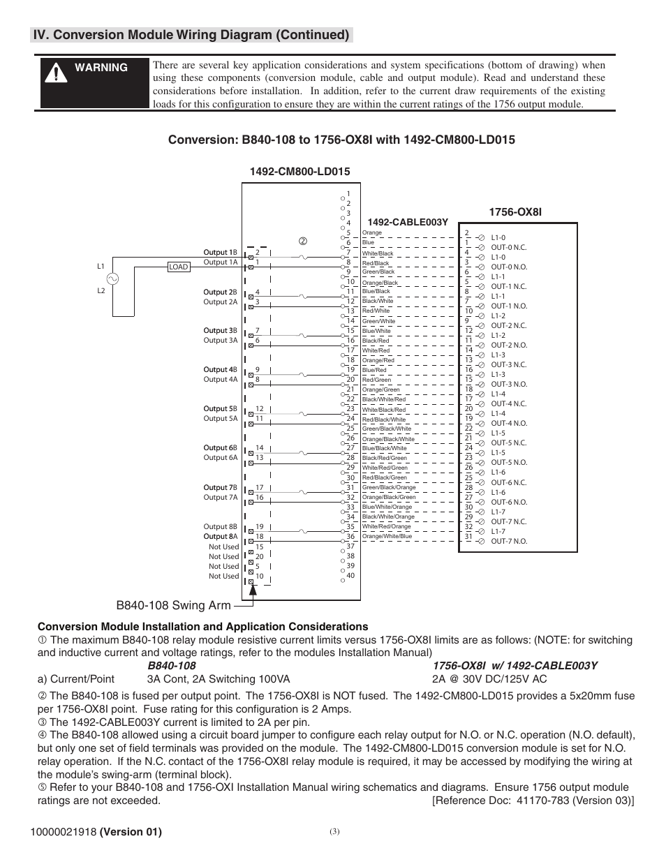
Iv Conversion Module Wiring Diagram Continued Rockwell Automation 1492 Cm800 Ld015 Field Wire Conv Module For Modicon B814 108 Or B840 108 To 1756 Ox8i User Manual Page 3 8 Original Mode

Vi Wiring Diagrams Cont D Rockwell Automation 1492 Cm1771 Ld0012 Field Wire Conversion Module User Manual Page 13 16
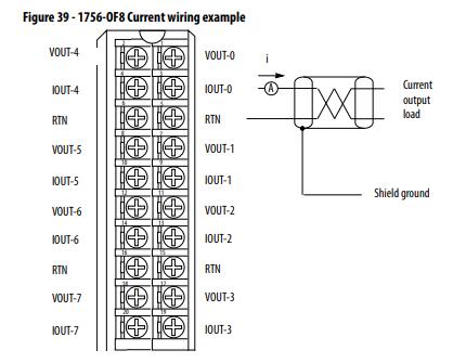
Allen Bradley 1756 Of8 1756 Of4 1756 Of4k 1756 Of8i 1756 Output Module Oleh Pt Total Abadi Solusindo Authorized Distributor General Contractor Di Jakarta Timur
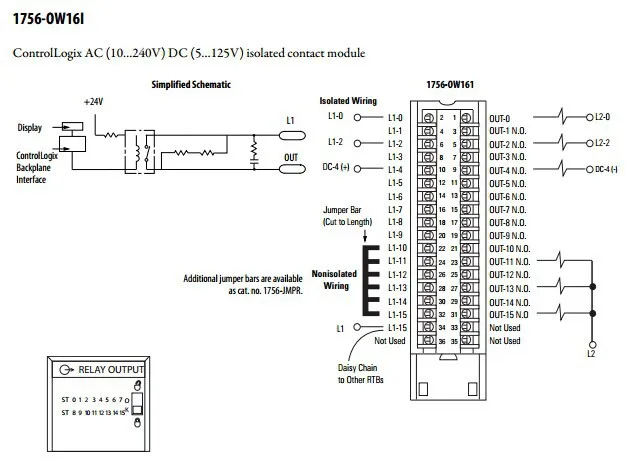
Allen Bradley Plc Pemrograman 1756 Ow16i 16 N O Output Terisolasi Terpisah Dengan Harga Terbaik Buy Ac Dc Terisolasi Hubungi Modul Analog Output Modul Plc Pengukur Amper Dengan Output Product On Alibaba Com

Iv Conversion Module Wiring Diagram Rockwell Automation 1492 Cm800 Ld015 Field Wire Conv Module For Modicon B814 108 Or B840 108 To 1756 Ox8i User Manual Page 2 8
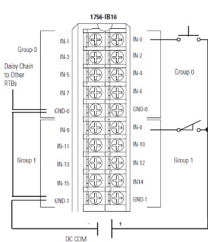
1756 Ib16 Allen Bradley Controllogix Digital I O Modules

1756 Ox8i Rockwell Automation 1756 Xxxx Controllogix Digital I O Modules User Manual Page 175 258
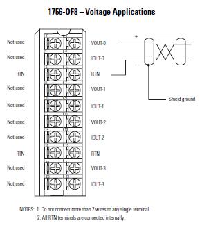
Allen Bradley 1756 Of8 1756 Of4 1756 Of4k 1756 Of8i 1756 Output Module Oleh Pt Total Abadi Solusindo Authorized Distributor General Contractor Di Jakarta Timur
