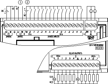
Digital inputs can be used as HSC at kHz. CPU 1214C ACDCRelay 6ES7 214-1BG40-0XB0 24 VDC Sensor Power Out For additional noise immunity connect M to chassis ground even if not using sensor supply.
6es7214 1hg40 0xb0 Wiring Diagram - If you're searching for video and picture information linked to the keyword you've come to visit the ideal site. Our site provides you with hints for seeing the maximum quality video and image content, hunt and find more informative video content and graphics that fit your interests. includes one of tens of thousands of video collections from several sources, especially Youtube, so we recommend this video that you view. This blog is for them to stop by this site.
Get 6es7214 1hg40 0xb0 Wiring Diagram Pictures Trailer Wiring Diagram
CPU C ACDCRelay 6ES7 1BGXB0.

6es7214 1hg40 0xb0 wiring diagram. 2-wire sensor Yes 1st interface Interface type PROFINET Physics Ethernet Isolated Yes Automatic detection of transmission speed Yes Autonegotiation Yes Autocrossing Yes Functionality PROFINET IO Device Yes PROFINET IO Controller Yes PROFINET IO Controller Transmission rate max. A wiring diagram usually gives guidance about the relative approach and arrangement of devices and. 05 A 2 s.
DQ 10xRLY 30 V DC V AC 2 A AI 2x10 Bit 010 V DC. 6es7215 1ag40 0xb0 Wiring Diagram Pdf.
2 AI 0-10 V DC Power supply. X CPU C ACDCRelay 6ES7 BGXB0 SIMATIC S7 S Programmable controller CPU C wiring diagrams. Goreng 24 Aug 2019 0.
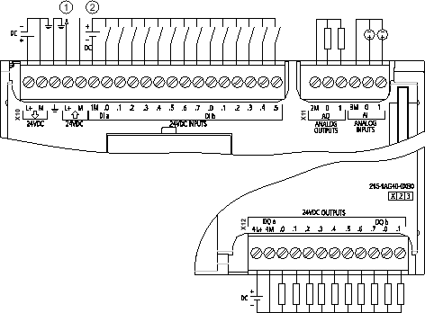
CPU 1214C DCDCRelay 14DI10DO2AI - 6ES7214-1HG40-0XB0 - Industry Support Siemens. SIMATIC S7-1200 series with 1214C CPU 24VDC power supply 14 24VDC inputs 10 relay outputs 2 analog inputs 010V and the possibility to install 8 additional extensions. For sinking inputs connect - to M shown.
Home 6es7215-1ag40-0xb0 wiring diagram pdf. The resorts cottages and hotels in Kausani provide great ambience and beautiful surroundings which will further add delight to your vacation. Siemens Industry Online Support.
For sourcing inputs connect to M. Corrections to wiring diagrams. Siemens Industry Online Support.
6ESBGXB0 - CPU C - 85 VAC PSU 14 DI 24 VDC 10 Relay DQ 2 AI V kB. X11 connectors must be gold. CPU 1214C Wiring Diagrams Table 1 CPU 1214C ACDCRelay 6ES7 214-1BG31-0XB0 ① 24 VDC Sensor Power Out For additional noise immunity connect M to chassis ground even if not using sensor supply.
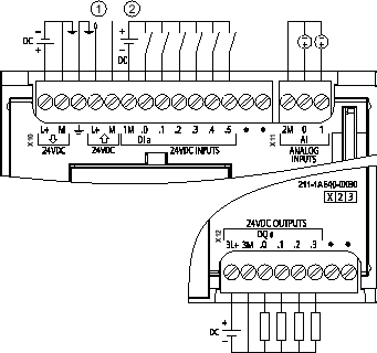
The Goibibo app displays all these accommodation types under specific. CPU 1214C DCDCDC 14DI10DO2AI - 6ES7214-1AG40-0XB0 - Industry Support Siemens. 6ES7 HEXB0 CPU ACDCRly 6ES7 BGXB0 CPU C ACDCRelay 6ES7 BGXB0 SIMATIC S7 S Programmable controller CPU C wiring diagrams Pin X10 X11 gold X12 Abstract.
100 50 mA. See Appendix C Spare. DC 204-288V DC Programdata memory 100 KB.
10 DO relay 2 A. 6ES7 KFAB0 KBAB0 Wiring Diagram 6es7 BcXB0 siemens S cpu 6ES7 BcXB0 siemens s7. 110 x 100 x 75 mm.
25052019 25052019 4 Comments on 6es7214-1bg40-0xb0 Wiring Diagram. 6Es7214 1Bg40 0Xb0 Wiring Diagram. 100 Mbits 6ES7215-1HG40-0XB0 Changes preserved.
Your shopping destination for industrial automation. 6ESBGXB0 - CPU C - 85 VAC PSU 14 DI 24 VDC 10 Relay DQ 2 AI V kB. SM 1232 and SM 1234 Page 13 Communications connections Page 14 Update to the S7-1200 System Manual edition 092016 2 A5E03929122-AN 022018.
6es7231 4hd32 0xb0 Wiring Diagram wiring diagram is a simplified customary pictorial representation of an electrical circuit. Between the channels in groups of 2 Permissible potential difference between different circuits 500 V DC between 24 V DC and 5 V DC EMC Interference immunity against discharge of static electricity. To enjoy sightseeing and adventure sports you must visit the place in the summer months.
X11 connectors must be gold. CPU 1214C wiring diagrams Table 1. 6es7214-1bg40-0xb0 Wiring Diagram.
CPU 1214C wiring diagrams. Podstawowy Plc Profinet 2xrj45 14we 10wy Cyfr 2we 2wy Analog 24v Dc 125kb Simatic S7 1200 Cpu 1217c 6es7217 1ag40 0xb0 Siemens 52 Fresh 6es7214 1ag40 0xb0 Datasheet Friv2hub Cpu 315 2pn Dp Datasheet Great Simatic S7 300 Cpu 315 2 Pn. 6ESBG front and 5 cabling diagrams per front door Wiring of SIMATIC S7 IO modules with the sensorsactuators is.
Variables Inputsoutputs memory bits DBs distributed IOs timers counters Forcing Forcing Yes Diagnostic buffer present Yes Traces Number of configurable Traces. 6es7214-1hg40-0xb0 Product Description SIMATIC S7-1200 CPU 1214C compact CPU DCDCrelay onboard IO. For sourcing inputs connect to M.
It shows the components of the circuit as simplified shapes and the capability and signal contacts amid the devices. 24 VDC Sensor Power Out For additional noise.
05 A 2 s CPU 1214C DCDCDC 6ES7214-1AG40-0XB0. CPU C wiring diagrams. CPU C DCDCRLY Supply 24 V DC DI 14x24 V DC.
14 DI 24 V DC. 6es7214 1bg40 0xb0 Wiring Diagram including wiring diagrams parameter descriptions n Sample configurations. 8 signal modules and 1 signal boardcommunication board.
For sourcing inputs connect to M. X11 connectors must be gold. CPU 1215C Wiring Diagrams Table 1 CPU 1215C ACDCRelay 6ES7 215-1BG31-0XB0 ① 24 VDC Sensor Power Out For additional noise immunity connect M to chassis ground even if not using sensor supply.
6es7214 1bg40 0xb0 Wiring Diagram. Buy Now Siemens 6ES7214-1HG40-0XB0 brand new guaranteed at the best price. 6es7214-1bg40-0xb0 Wiring Diagram.
The design of a SIMATIC S station and in the easy.

Simatic Flip Book Pages 1 4 Pubhtml5
Https Support Industry Siemens Com Cs Attachments 109743003 S71200 Manual Update En Us En Us Pdf Download True
Cpu 1214c Wiring Diagrams Simatic S7 S7 1200 Programmable Controller Id 91696622 Industry Support Siemens

Simatic S7 S7 1200 Programmable Controller Cpu 1214c Wiring Diagrams 34m7ejv7jo46
Simatic S7 S7 1200 Programmable Controller Cpu 1214c Wiring Diagrams Relay Electrical Components
Cpu 1211 Wiring Diagrams Simatic S7 S7 1200 Programmable Controller Id 91696622 Industry Support Siemens

Simatic Flip Book Pages 1 4 Pubhtml5
Simatic S7 S7 1200 Programmable Controller Cpu 1214c Wiring Diagrams Relay Electrical Components
Https Support Industry Siemens Com Cs Attachments 109743003 S71200 Manual Update En Us En Us Pdf Download True
