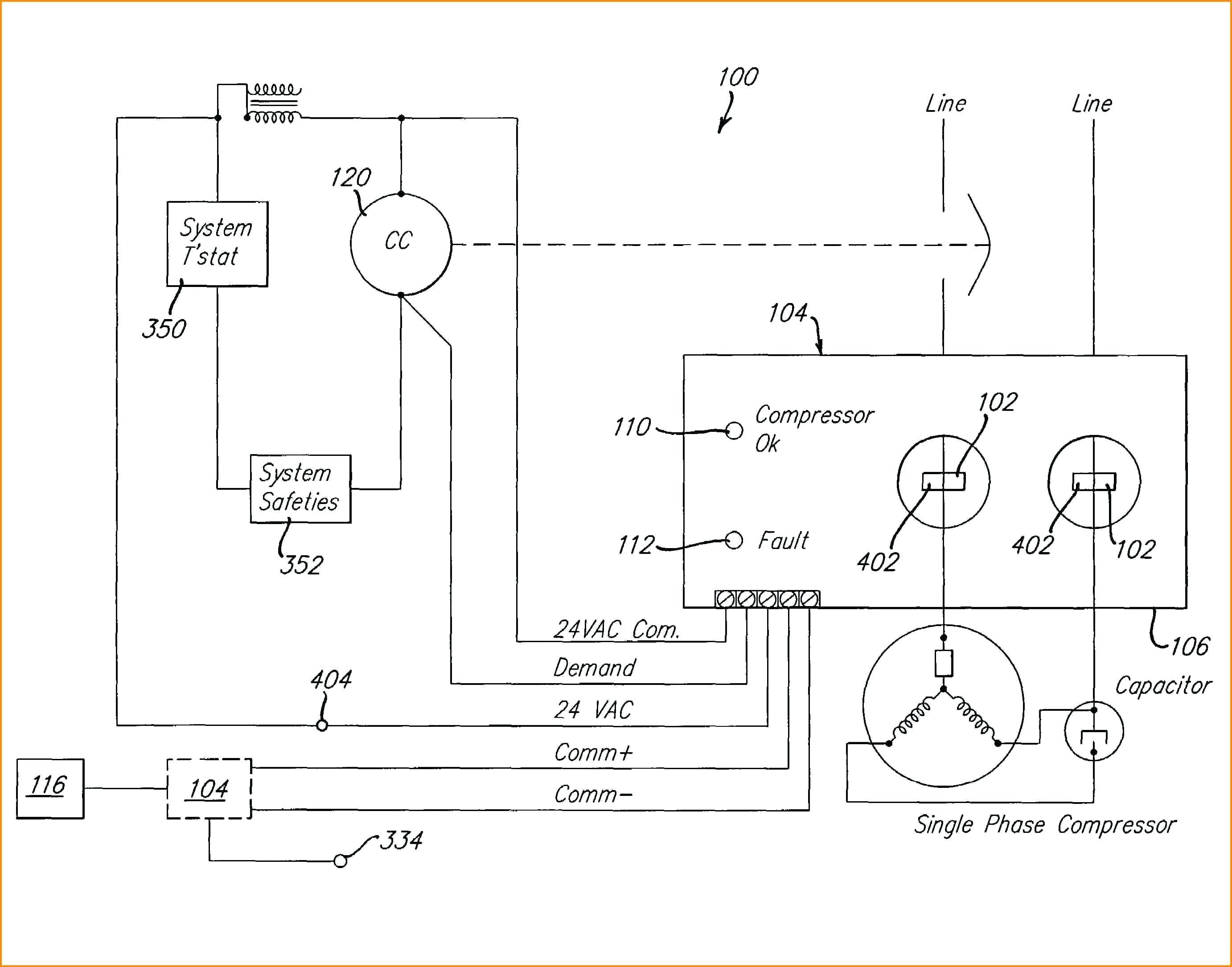
C. 2 Duplex unit system diagram.
Duplex Air Compressor Wiring Diagram - If you're looking for video and picture information linked to the key word you've come to visit the ideal site. Our site gives you hints for seeing the highest quality video and picture content, search and find more enlightening video articles and images that fit your interests. includes one of tens of thousands of movie collections from various sources, especially Youtube, so we recommend this video for you to see. It is also possible to contribute to supporting this site by sharing videos and images that you like on this blog on your social media accounts like Facebook and Instagram or tell your closest friends share your experiences concerning the simplicity of access to downloads and the information you get on this website. This site is for them to stop by this site.
Acp Duplex Compressor Units
Air compressor relieve pressure and unplug the air compressor from the power source.
Duplex air compressor wiring diagram. The next time there is a demand for compressed air the lead pressure switch detects the demand pressure switch contacts close and an alternate compressor in the system starts and runs until the demand is met. Injunction of two wires is generally indicated by black dot to the intersection of 2 lines. Wiring Diagram Pics Detail.
In a duplex unit there are two. Champion R-Series Compressors have a time-tested proven design. While pump A is on pump B is inhibited from being turned on by the state of the flip-flop.
Compressor pump x2 ASME air receiver with safety valve Electric motor x2 Starter x2 Pressure switch x2 Hour meter Shut-off valve Deluxe Alternator Control Panel Quick Reference Recommended Oil 2 Options Single viscosity SAE 30 ISO100 nondetergent compressor. Follow the safety precautions for electrical connections. At times the cables will cross.
Variety of air compressor pressure switch wiring diagram. Wiring Diagram Images Detail. 6 Wiring 7 Starting the Compressor 8 Fully Packaged and QP Compressor Section 9 Troubleshooting Guide.
Before servicing air compressor. 03041996 ecn12-98 1 added optional lead-lag selector switch da 6-30-97. This video is i.
As stated previous the lines in a Air Compressor Wiring Diagram signifies wires. This video is by a common request that goes over a basic wiring diagram for a magnetic starter used for a 2 stage air compressor application. Air compressor magnetic starter wiring duration.
Allow air compressor to cool down. It could restart at any time. SBD 10-15 Dryer Manual 366 Mb.
Air compressor control wiring diagram. See Figure 1-1 for simplex wiring diagram and Figure 1-2 for duplex wiring diagram. Is your logical goal as follows.
READ ALL SAFETY WARNINGS BEFORE USING AIR COMPRESSOR. Depending on how far the actual pressure is below your desired cut-in pressure turn the screw a little further quarter-turn or less. Arb part 180409 air compressor loom wiring diagram.
Variety of air compressor wiring diagram 230v 1 phase. OVERLOAD HI TEMP LOW OIL. We will start with the flip-flop allowing pump A to function.
SBD 25-75 Dryer Manual 394 Mb. If ordered with a factory mounted magnetic starter compressor is wired at factory. Desicant Dryer Manual DHW5-25 142 Mb.
Now the cut-in pressure should already be more-or-less OK. But it does not imply link between the cables. There will be main lines that are represented by L1 L2 L3 and so on.
Never assume the air compressor is safe to work on just because it is not operating. Remove wire between terminal 2 1and alternator contact wire as shown below optional between terminals remove jumper ox 0x on-off switch 5 off 3 off on 6 4 on a gardner denver company princeton il. Variety of ingersoll rand air compressor wiring diagram.
Pump A turns on at its low pressure threshold. The units consist of two equally rated motor-compressor assemblies mounted on a single ASME tank. Filter and Dryer Manuals.
The pressure rises opening the lead pressure switch de-energizing the alternator relay and the 1st air compressor. The arb ckma12 and ckma24 compressor kits were designed specifically as a versatile quick installing compact yet high flow air source to suit the arb air locker which also suits the harsh and. The alternator will then alternate from the 1st air compressor to the 2nd air compressor ready for the.
Two Stage Splash Lubricated 2-30 HP Reciprocating Air Compressor. Service in a clean dry flat area. The AD Series Powerex Duplex Air Compressors have been designed broken-in and tested to meet the most demanding specifi cations for low oil carryover and long life in the pneumatic climate control industry.
A wiring diagram is a simplified traditional pictorial depiction of an electric circuit. Duplex Compressor Sequence of Operations 1. HIT Dryer Manual 168 Mb.
Duplex units operate in much the same way as simplex units only there are two compressors. 4500-9000 Series Manual 347 Mb. Figure 1 - Simplex Wiring Diagram 305CAS546-B Ref.
Air compressor wiring diagram 230v 1 phase Air pressor Wiring Diagram 230v 1 Phase Download. The Speedaire Two Stage Duplex Air Compressors are two stage oil lubricated reciprocating compressors. Duplex - 1 NPT.
Refer to the simplex diagram for a description of the compression cycle. Slightly open drain cock after shutting off compressor. Reciprocating Air Compressor Manuals.
SBD 100-425 Dryer Manual 690 Mb. The controls continue to select an alternate compressor to operate when the next demand for compressed air occurs. A flip-flop circuit a bi-stable device determines which pump can turn on.
Sometimes wiring diagram may also refer to the architectural wiring program. Rugged standard features a wide selection of configurations and quality available options make the R-Series compressors the solution to. 700 Series Manual 181 Mb.
1 Compressor 821312202700 821312202700 821312202700 821312202700 821312202700 2 Motor 821312101600 821312101600 821312101600 821312101600 821312101600 3 Tank 821312201200. Ecn32-96 released none diagram wiring duplex control panel b647 1 of 1 mdh. The key difference is in the pressure switch and starter.
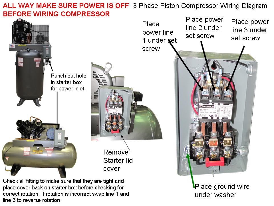
It is necessary only to bring lines from a properly sized disconnect switch to the magnetic starter mounted on the unit. Air compressor pressure switch wiring diagram square d air pressor pressure switch wiring diagram Download Pressure Switch Wiring Diagram Air pressor. Dur-O-Line Series Manual 189 Mb.
Now adjust the set-screw the big one clock-wise increase cut-in pressure until the compressor starts. The lead pressure switch closes energizing the alternator relay and 1st air compressor.
Champion Hra15d 25 Duplex 15 Hp Piston Air Compressor 107 4 Cfm 175 770 Rpm 208 230 460 Volt 3 Phase
Https Industrialgold Com Assets Downloads Technical Manuals Reciprocating 7 5 Recip Duplex Special Ig Pdf
Technical Document Compressed Air Systems
Technical Document Compressed Air Systems
Diagram Quincy Duplex Air Compressor Wiring Diagram Full Version Hd Quality Wiring Diagram Nidiagram Masteruninauto It
Spring Summer 2017 Catalog Air Compressor Sales Inc By Air Compressor Sales Inc Issuu
Wiring Ingersoll Rand Replacement Control Box Diy Home Improvement Forum
Quincy Qt Splash Lubricated Duplex Air Compressor 7 5 Hp 460 Volt 3 Phase 120 Gallon Horizontal Model 273dc12dc46
Ul Duplex Saylor Beall


