Plan 1S for house using 3 201 phones. The old model is below.
Entryphone London Wiring Diagram - If you're searching for picture and video information related to the key word you have come to visit the ideal site. Our site gives you hints for seeing the highest quality video and picture content, search and find more enlightening video content and graphics that fit your interests. includes one of thousands of movie collections from several sources, particularly Youtube, therefore we recommend this video that you see. This blog is for them to stop by this site.
Entryphone Door Entry Systems
Entryphone Of London 201 Terminals L Speech In Speaker P Speech Out Mic BFG Common A2 Call 1 Lock Button 1 2 Button 2 IMPORTANT NOTE.

Entryphone london wiring diagram. Basic 1 Button Audio Kit. 020 8874 0066 entryphonecouk The 99VRU relay is for use where it is required for two doors to be answered by the same telephones. Engineers Area Staff Only Farfisa.
GEC222210 Electric locomotive schematic diagram of air system air brake pipe and conduit arrangements. 020 8870 8635 Fax. Orbit 6-Station Easy-Dial Sprinkler Timer-57876 The Home Depot Orbit Sprinkler Wiring Diagram.
Old phone is wired. I have managed to find for example that the common goes to 6 ringer to. Plan 31 for 3 flats with 3 doors using 201 phones.
1 Before replacing the handset make note of the wires to each terminal on the existing unit an easy way. Engineers Area Staff Only LT Terraneo. Plan 21 Entryphone 200 series Video Wiring Diagram Door The Entryphone CoLtd.
Noralsy keypad manual MICA 30 Code 1 relay. View as Grid List. Having opened it up unfortunately Im not sure which wires go to which connectors.
2 Way Switcher diagram. Engineers Area Staff Only Fermax. The bell phone is marked I R O T and Z.
It provides communication between an entrance and. Entryphone Of London 8022 Terminals L Speech In Speaker P Speech Out Mic BFG Common A Call 3 Lock Button 1 8 Button 2 IMPORTANT NOTE. Where a building has a front and a rear entrance.
23 Granville Road London SW18 5SD. GEC22221 Mechanical details for a variety of locomotives. Engineers Area Staff Only GDX.
1 Before replacing the handset make note of the wires to each terminal on the existing unit an easy way. I is R is O is T is Z is Many thanks Benjamin. 23 Granville Road London SW18 5SD Tel.
SRS audio installation diagram with explanation of the cables and functions. I pulled off my entry phone to repaint the wall and lost my diagram i had made. We recommend that you change handsets with Entryphone of London products if changing over for another manufacturers handset you will find that outward speech level is reduced considerably.
Entryphone technical Compatibility of audio handsets plan 1 41wire All audio 41 our handsets are compatible with each other. GEC222208 3 coach electric train set diagram. N way 1 entrance with extension bell SRS audio installation diagram.
SRS audio installation diagram. Entryphone Door Entry Systems. Tone Call entrance 1 and Buzzer call from entrance 2.
020 8870 8635 f. SRS audio installation diagram for two phones audio intercom kit. As we routinely add new products you can keep coming back here for new diagrams.
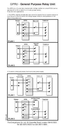
Wiring Diagram Basic 1 Way Audio 2 Entrance System with 99RU Relay NOTE. Plan 22 for 2 flats with 2 doors and porter intercom using 202204 phones. We distribute a huge range of Bitron products from their intercoms to advanced IP video entry systems as a result of this we hold many supporting documents.
1 way 2 entrances with DC50 keypad. The terminals BFGL and P are common to all handsets please note that the installer must link B F and G in each handset. 500 Series Video Schematics connection diagrams and installers notes For the system installed at.
Trying to replace an old entryphone photo and wiring in new phone. 020 8874 0066 e. Plan 23 for 3 flats with 2 doors with full intercom using 204 phones.
Entryphone The Entryphone Company Limited 23 Granville Road London SW18 5SD t. The new model is a Bell 801 door entry telephone. Entryphone Of London 8802 Terminals L Speech In Speaker P Speech Out Mic BFG Common A Call 3 Lock Button 1 8 Button 2 IMPORTANT NOTE.
Plan 31 for 6 flats master and 2 slave doors using 201 phones. Green terminal 2 Blue in terminal 10 White in terminal 9 Red in terminal 1 Yellow in unnumbered junction Black is loosespare So Im now trying to match the five colours to the 5 Bell terminals. 1 Before replacing the handset make note of the wires to each terminal on the existing unit an easy way.
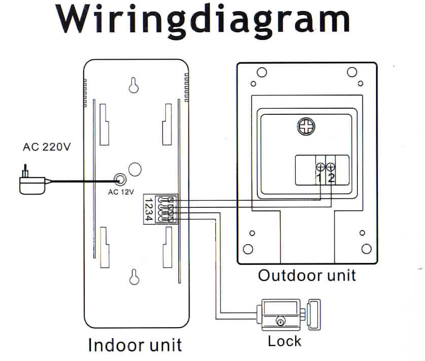
Wiring Diagram consists of many in depth illustrations that display the connection of assorted items. Wwwentryphonecouk ENTRYPHONE is a trade mark registered in Britain No. Wiring diagrams for Entryphone products.
- a white and green wire. - a white wire. Operation Plan 1 is the most common form of system found.
Mon-Thu 9am-5pm Fri 9am-430pm. It contains instructions and diagrams for various types of wiring techniques along with other items like lights windows and so on. Engineers Area Staff Only ISM.
Engineers Area Staff Only Noralsy. GEC222209 Pipe arrangement end views. Plan 1 Entryphone Audio Wiring Diagram with 201S Telephones Door The list below indicates the function of each terminal this provides useful reference particularly for tracing faults or for a fuller understanding of how the system works.
Here you will find our Bitron wiring diagrams that we been accumulating over the years.
Privacy Settings
Kit1fapt 2 Wire Door Phone Entry System Non Expandable
Https Www Intercomsrus Com Handset 20pdf Entryphone 208802 20intercom 20handset 20data 20sheet Pdf
Entryphone Door Entry Systems
Entryphone Door Entry Systems
Https Www Intercomsrus Com Handset 20pdf Entryphone 20201 20door 20entry 20handset 20data 20sheet Pdf
Entryphone Door Entry Systems
Entryphone Door Entry Systems
Entryphone Door Entry Systems


