Continuous Rating The constant load which a transformer can carry its rated primary voltage and frequency without exceeding its specified temperature rise. The KVA capacity of the transformer must equal or be greater than the load rating.
600v To 120v Transformer Wiring Diagram - If you're looking for video and picture information related to the keyword you have come to visit the ideal blog. Our website provides you with hints for seeing the maximum quality video and image content, hunt and locate more enlightening video articles and graphics that match your interests. comprises one of tens of thousands of movie collections from several sources, especially Youtube, therefore we recommend this video for you to view. This blog is for them to visit this site.
Pin On Electrical Code
Secondary Max Current Amps.

600v to 120v transformer wiring diagram. None X4X1 H4 H3H2 H1 X2 X3 PRIMARY. Full Load Current Ratings. 480 volt to 120 volt transformer wiring diagram Booster Transformer 600v To 480v Single Phase Three Pdf Types And 480V 120V Wiring Diagram.
This document contains wiring diagrams enclosure diagrams and accessories application data and specifications for sealed low voltage transformers. 12 2 2 ANFC 4 2 12 BNFC X4 X1 H10 H2 H3 H1 X2 X3 H5 H6 H4 H7 H8 H9. A wiring diagram normally provides information about the relative position and also setup of devices and also terminals on the tools in order to help in structure or servicing the gadget.
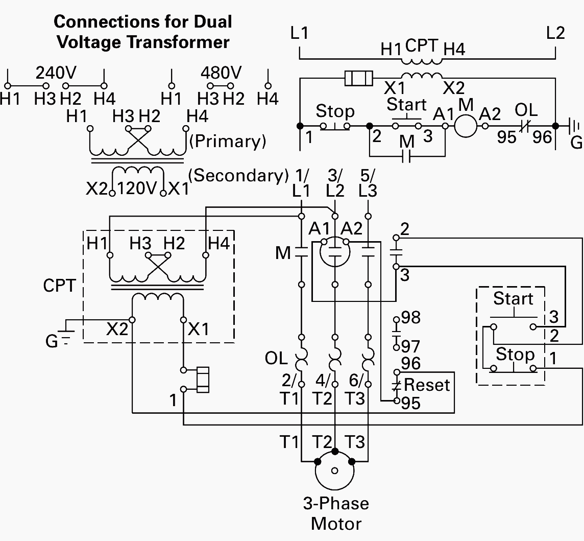
It shows the elements of the circuit as streamlined forms and also the power as well as signal connections in between the devices. Figure 3 shows a basic control circuit with a step-down transformer added. None X4 X1 H4 H3 H2 H1 X2 X3 ConnectConnect Primary Primary Inter- Secondary Volts Lines To Connect Lines To 240 H1-H4 H2 to H3 120 H1-H3 H2-H4 Secondary Volts 240 X2 to X3 X1-X4 120240 X2 to X3 X1-X2-X4 120 X1 to X3 X1-X4 X2 to X4 PRIMARY.
Single-Phase KVA Volts x Load Amperes 1000. TEMCo Medium Voltage Isolation Transformers are designed for stepping down incoming higher voltage power to utilize voltages for commercial institutional or industrial applications. 800 x 600 px source.
The range of products covered by DOE 2016 is. 833A at 120 Volt or 417A at 240 Volt. These transformers CANNOT be used for reverse feed.
HPS Imperator tm Industrial Control Transformer Wiring Diagrams Issue Date. It reveals the parts of the circuit as streamlined forms as well as the power and also signal links between the gadgets. If you have any questions regarding these wiring diagrams or are having any difficulty correctly installing our transformers please contact HPS customer service or technical support in the US.
At 1-866-705-4684 or in Canada at 1-888-798-8882. 2120240 is for 3 wire or 2 wire secondary. October 2007 rev4 Page 1 of 9.
120 240v single phase transformer wiring diagram. GENERAL ACME TRANSFORMER WIRING DIAGRAMS PRIMARY. Control transformer wiring diagram Booster Transformer 600v To 480v Single Phase Three Pdf Types And 480V 120V Wiring Diagram.
Transformer To Wiring ImageResizerTool Com November 23rd - to transformer wiring diagram as well asGENERAL ELECTRICAL CONNECTION DIAGRAMSACME TRANSFORMER WIRING DIAGRAMS PRIMARY. INDUCTORS TRANSFORMERS OVERLOAD RELAYS AC MOTORS DC MOTORS WIRING CAPACITORS RESISTORS SEMICONDUCTORS Table 1 Standard Elementary Diagram Symbols contd Iron Core Air Core Auto Iron Core Air Core Current Dual Voltage Thermal Magnetic Single Phase 3-Phase Squirrel Cage 2-Phase 4-Wire Wound Rotor Armature Shunt Field show 4 loops Series. A transformer with a turns ratio which provides a higher than rated voltage at no load and rated voltage at rated load.
Assortment of 75 kva transformer wiring diagram. The NEMA 3R ventilated enclosure makes it suitable for indoor use as well as outdoor protection against rain and sleet. Primary Max Current Amps.
The primary winding of the transformer is connected to two phases of the power circuit. Always use wiring diagram supplied on motor nameplate. Liquid-filled transformers below 10 kVA.
General Purpose Copper Coil Single-Phase DOE 2016 Efficiency Common Transformers. Collection of 480 volt to 120 volt transformer wiring diagram. The secondary winding is.
A wiring diagram is a streamlined standard pictorial depiction of an electrical circuit. The dashed lines indicate the transformer outlines. Transformers are optimized to offer maximum efficiency at 35 of nameplate rating.
Our transformers are built to last guaranteed. DOE 2016 Product Range Transformers that are currently specifically excluded from the scope of CFR Title 10 Chapter II Part 431 Appendix A of Subpart K 2016 include. Have a single phase 3 wire 120v 240v service.
75 kva transformer wiring diagram Hvac Transformer Wiring Diagram Inspirationa Wiring Diagram Auto Transformer Starter Save Acme Transformers. 1See page 10-43 and 10-44 for wiring diagrams. A wiring diagram is a streamlined traditional pictorial representation of an electrical circuit.
120 x 240 SECONDARY. 120x240 is for 2 wire secondary only. Figure 2 DeltaDelta Transformer Connections click to expand diagram The connection diagram on the left shows how a deltadelta connection can be made either with three single-phase transformers or with one three-phase transformer.
Note that the main motor circuit operates at 480V while the control circuit is at 120V. Select a transformer model using the Quick Selection Guide for the desired transformer type.
31 How To Wire A Xj3 D Brand Chint Phase Failure And Phase Sequence Protective Relay Device Youtube Relay Failure Wire
Wiring Of Control Power Transformer For Motor Control Circuits Eep
Portal News M 3 Jenis 600 Volt Di Hook Up Kawat Home Electrical Wiring Electrical Circuit Diagram Electrical Engineering Books
What Is Motor Starter Types Of Motor Starters Electrical Technology Electrical Circuit Diagram Basic Electronic Circuits Electrical Diagram
3 Phase Wye With Neutral Electrical Engineering Books Electrical Circuit Diagram Home Electrical Wiring
How To Wire 3 Phase Electric
Doe Transformer Literature Federal Pacific
Pin By Laszlo Bodo On Aramkorok Circuit Diagram Inverter Circuit Sine Wave Inverter Circuit Diagram
Hps Spartan Wiring Hammond Power Solutions


