BLR-CX-R BLR-CX-T Rev. 2 Combo Switch 2 x 4 Narrow Push to Open.
Cx 12 Wiring Diagram - If you're searching for video and picture information linked to the key word you have come to pay a visit to the ideal blog. Our website gives you suggestions for seeing the maximum quality video and picture content, hunt and find more enlightening video content and graphics that match your interests. includes one of thousands of movie collections from various sources, particularly Youtube, therefore we recommend this video that you view. You can also bring about supporting this site by sharing videos and images that you enjoy on this site on your social networking accounts such as Facebook and Instagram or tell your closest friends share your experiences concerning the simplicity of access to downloads and the information you get on this website. This blog is for them to visit this website.
Camden Cx Wc14 Restroom System Sacelec
CX-WC12 Wiring Diagram PDF CX-WC12 Wiring Diagram French PDF CX-WC16.

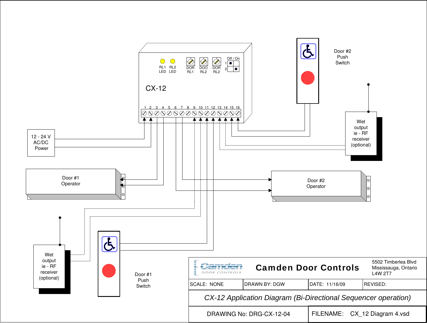
Cx 12 wiring diagram. 1 CM-AF540SO Double gang SS faceplate pushpull mushroom push button red Assistance Required w LED annunciator and adjustable sounder Assistance Requested. Refer to Diagram 3 Page 11 for the following connections. The CX-12 has been designed for.
Wire the outputs as shown. Wire the respective door contact switches to Inputs 3 4. Commercial Series Data Sheet CX-6 CX-12 User Manual.
CX-12 Plus Door Interface Relay has 8 programming modes with 3 adjustable time delays each up to 30 seconds. Wire the activating devices for Door 1 to DRY 1 terminals. Camden Door Controls CX-12 switching network is an economical door interface relay.
Mississauga Ontario L4W 2T7 12 - 24 V ACDC Power Electric Strike Door Operator MOV Wire MOV supplied directly to strike or magnet Power. The CX Commercial Lighting Control Panel is a self-contained lighting control system that replaces conventional timeclock and contactor combinations with a labor saving simple and flexible module solution. CX provides a reliable standalone relay control solution to reduce energy consumption for small and intermediate size projects that are.
Pushbutton Annunciator System. Approvals Certifications 6 Series UL 61010-1 Compliance Certificate. The contact circuit must be closed when the door is closed.
Information contained in service manuals typically includes schematics circuit diagrams wiring diagrams block diagrams printed wiring boards exploded views parts list disassembly assembly pcb. Camden CX-WC Series Barrier Free Restroom Control WC-13-AX WEC-10-K2 Wiring Diagram. The end connector of the ribbon cable is slotted and should not be forced into place.
Touchless Switch Restroom System. 5A SPDT Fan control relay 05A NO. The release of CX-12 Plus Door Interface Relay makes CX-12 and CX-22 model relays obsolete.
4 ½ Push Plate Annunciator System. CX-91S and 92S-06_Manual_R2 PDF CX-91S and 92S-12_Manual_R2 PDF CX-93 Series. If installed wire your safety device directly to the operator control box as per usual.
Emergency Call System Kit For 2 Door Restrooms w Multi-Color Dome Light. Camden Manufacturing 5502 Timberlea Blvd. CX-12 PLUS DOOR INTERFACE RELAY INSTALLATION INSTRUCTIONS Note.
2 Universal electric strike 1224V ACDC fail safefail secure operation horizontal adjustment cw 3 stainless steel faceplates CX-ESP1B ESP3B. View all of our product downloads here. Relay 2 has a delay on-operate of 0-30 seconds and delay-on-release of 0-30 seconds.
12-24VAC or 12-32VDC input. Murphy Switch Wiring Diagram Ignition System Distributor. Mazda Cx 5 Service Repair Manual Power Window System Glass.
CX-93M-12LS_Manual_R1 PDF CX-93M-12LS_Manual_French R1 PDF. Wire the activating devices for Door 2 to DRY 2 terminals. Connect the CX Controller Ribbon Cable into the CX Controller Ribbon Connector.
Camden CX 12 Switching Network Installation Instructions A128 Manual NF Rev1. Open the PDF directly. 07 2018-07 5 11 Wiring diagram BLR-CX-R PE control exits for fan controll BLR-CX-T external T K L Um1 Um2 M A T1 T2 MS 1 14 1-14 Controll exits can be parametered K1 K14 K1-K14 L1 L2 L3 N BLR-CX TTL X1A or X5A 15mA - 6A 90V - 550V power-input utility Interface load external temperature sensor or temperature switch.
In all instances the CX door is to be removed verify the panel is not energized. 2 CM-AF142SO Single Gang Multi-Color LED Dome Light w Sounder. Camden CX-WC Series Barrier Free Restroom Control WC-13-AX Wiring Diagram.
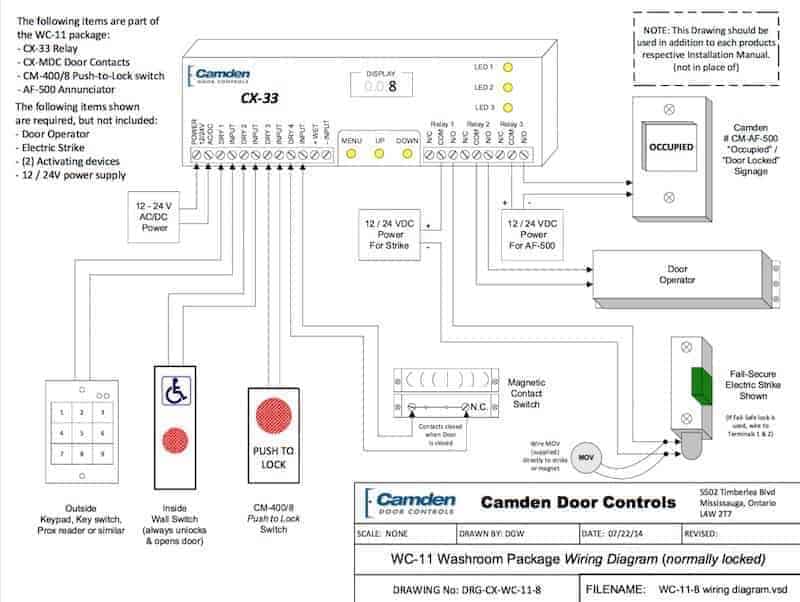
Catalyst 3560-CX and 2960-CX Switch Hardware Installation Guide 12 Product Overview Internal Power Supply. End of Life Notification. CX-WC11 Wiring Diagram PDF CX-WC11 Wiring Diagram French PDF CX-WC11 Riser Drawing PDF CX-WC11WEC10 Wiring Diagram PDF CX-WC11WEC10 Riser Drawing PDF CX-WC12.
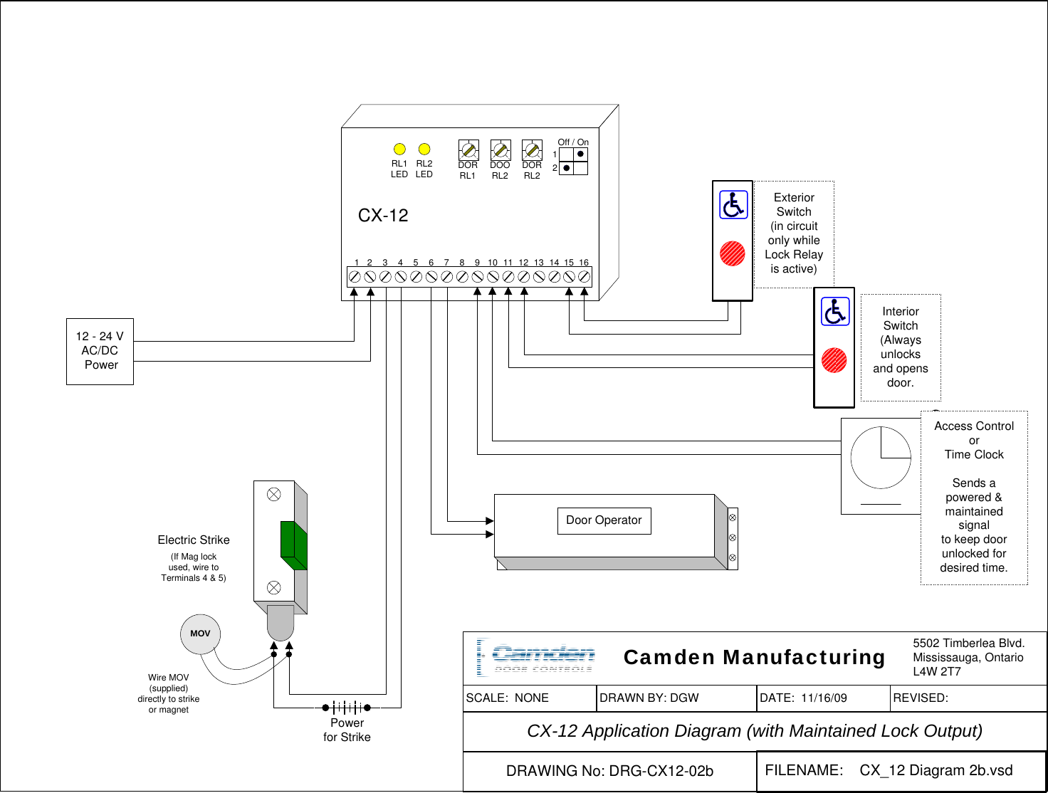
CX_12 Diagram 2bvsd CX-12 Application Diagram with Maintained Lock Output SCALE. HDR-CX11E HDR-CX12. CX-91S and 92S-12_Manual_R2 PDF CX-91S-12_Mounting Template PDF CX-91M-06_Manual PDF CX-90S-03_Manual_R1 PDF CX-90M-03_Manual_R1 PDF CX-92 Series.
There are 2 Dry and 2 Wet inputs with 2 SPDT Form C outputs. Digital Display for CO. Do not apply power to the unit until all secondary wiring.
1 CM-SE21A English solid. Camden CX-12 Switching Network Installation Instructions Instructions. Do not wire Safety devices to the CX-12.
Align the door hinge and the enclosure slide and rotate the door to slide into the hinge slot. 2 4-12 Push Plate Switch Wheelchair. Double Door Magnetic Locks.
Camden CX-WC Series Barrier Free Restroom Control WC-12 Wiring Diagram. Relay 1 has an adjustable delay-on-release of 0-30 seconds.
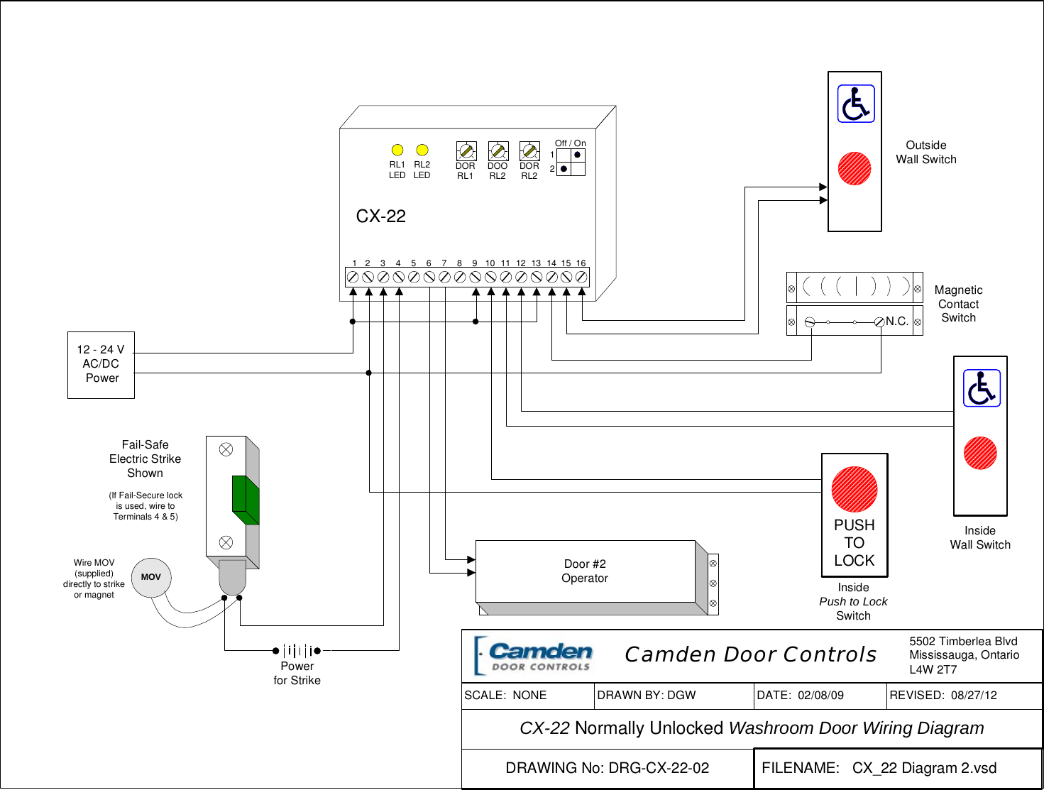
Camden For Use With Normally Locked Unlocked Washroom Doors And Fail Safe Or Secure Electric Locks Cx 22 Dual Function Relay Instructions A10341 Rev2 08282012
Wiring Help Wiring A Door Operator To A Washroom Kit General Access Control Discussion Cctvforum Com
Camden Cx 12 Switching Network Installation Instructions A128 Manual Nf Rev1
Camden Cx 12 Switching Network Installation Instructions A128 Manual Nf Rev1
Https Resources Locksandsafes Com Wp Content Uploads Camden Cx 12 Plus Door Interface Relay Installation Instructions Pdf
Camden Cx 12 Switching Network Installation Instructions A128 Manual Nf Rev1
Camden Cx Wc11 Push Button System Sacelec
Cx Manual Capacitor Switch
Camden Cx 12 Switching Network Installation Instructions A128 Manual Nf Rev1


